Sign In
Upload
Download
Table of Contents
Contents
Add to my manuals
Delete from my manuals
Share
URL of this page:
HTML Link:
Bookmark this page
Add
Manual will be automatically added to "My Manuals"
Print this page
×
Bookmark added
×
Added to my manuals
Manuals
Brands
Eaton Manuals
UPS
E Series DX
User manual
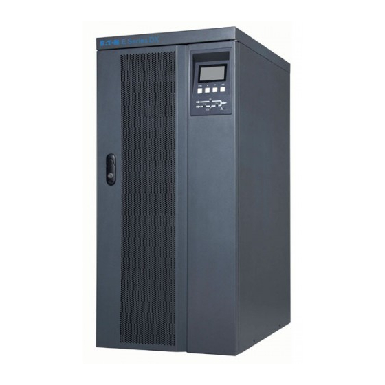
Eaton E Series DX User Manual
60-80kva (3-phase input/output)
Hide thumbs
Also See for E Series DX
:
Manual
(61 pages)
,
User manual
(26 pages)
1
2
3
4
5
Table Of Contents
6
7
8
9
10
11
12
13
14
15
16
17
18
19
20
21
22
23
24
25
26
27
28
29
30
31
32
33
34
35
36
37
38
39
page
of
39
Go
/
39
Contents
Table of Contents
Troubleshooting
Bookmarks
Table of Contents
Table of Contents
Chapter 1 B R I E F I N T R O D U C T I O N
Product Introduction
Frequently Used Symbols
Chapter 2 E X T E R I O R a P P E a R a N C E
Unpacking Inspection
Exterior Figure
Panel Instructions
Chapter 3 I N S T a L L a T I O N I N S T R U C T I O N S
Installation Notice
Installation Space
Installation and Wiring Connection Diagram
Requirements of Wiring Cables and Protect Device for EDX Series UPS
Parallel UPS Installation
Procedures of Connecting Battery Bank to UPS
Chapter 4 O P E R a T I O N
Single UPS Operation
Parallel UPS Operation
Chapter 5 C O M M U N I C a T I O N I N T E R F a C E
C Hap T er 6 O Pt Io N a L a C C E S S or I es
Transformer
Temperature Sensor
IP21 Option
Chapter 7 Transportation, Maintenance and Troubleshooting
Appe N D I X 1 te Ch ni Cal Par Amet E Rs and S Pe Cif Icatio Ns
A Ppe N DIX 2 D Is Pl Ay R E F E R E N C E T a B Le
Advertisement
Quick Links
1
Panel Instructions
2
Single Ups Operation
3
Chapter 7 Transportation, Maintenance and Troubleshooting
Download this manual
Eaton E Series DX
60-80kVA
(3-phase input/output)
User Manual
Table of
Contents
Previous
Page
Next
Page
1
2
3
4
5
Advertisement
Table of Contents
Need help?
Do you have a question about the E Series DX and is the answer not in the manual?
Ask a question
Questions and answers
Related Manuals for Eaton E Series DX
UPS Eaton E DX Series Manual
(61 pages)
UPS Eaton E DX Series User Manual
On line ups (26 pages)
UPS Eaton 700 Installation And User Manual
Pulsar series (200 pages)
UPS Eaton EX 700 Installation And User Manual
Eaton ex range pulsar series ups (27 pages)
UPS Eaton EX 2200 RT 2U Installation And User Manual
Pulsar series (172 pages)
UPS Eaton EX 2200 RT 3U Installation And User Manual
(172 pages)
UPS Eaton 500 Installation And User Manual
Protection station (29 pages)
UPS Eaton Ellipse ECO 500 Installation And User Manual
(8 pages)
UPS Eaton Ellipse ECO 500 Advanced User's Manual
(47 pages)
UPS Eaton Ellipse ECO 500 Installation And User Manual
(16 pages)
UPS Eaton Ellipse ECO 650 FR Installation And User Manual
(9 pages)
UPS Eaton 500 Installation And User Manual
(8 pages)
UPS Eaton Ellipse ECO 500 Installation And User Manual
(18 pages)
UPS Eaton Ellipse 375 Installation And User Manual
Pulsar series (9 pages)
UPS Eaton Pulsar Series Installation And User Manual
(40 pages)
UPS Eaton EX RT 5 Installation And User Manual
(38 pages)
This manual is also suitable for:
Edx 60kva
Edx 80kva
Table of Contents
Save PDF
Print
Rename the bookmark
Delete bookmark?
Delete from my manuals?
Login
Sign In
OR
Sign in with Facebook
Sign in with Google
Upload manual
Upload from disk
Upload from URL


Need help?
Do you have a question about the E Series DX and is the answer not in the manual?
Questions and answers