Table of Contents
Advertisement
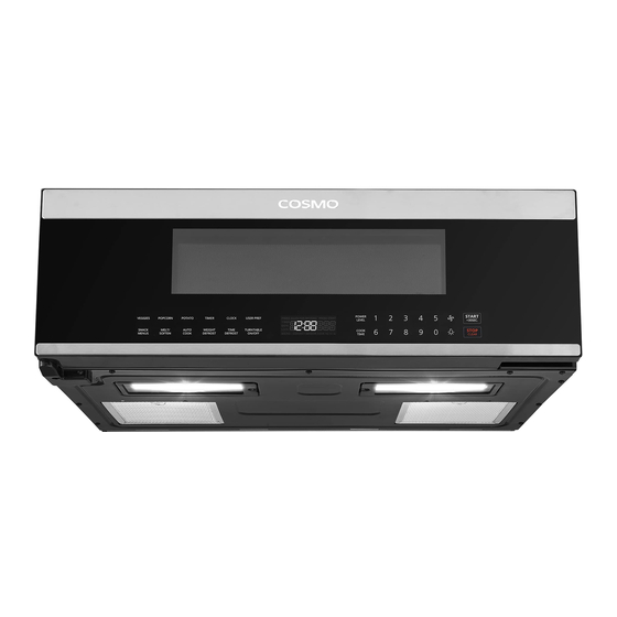
MICROWAVE OVEN
COS-3012ORLP1SS
OVER THE RANGE LOW PROFILE
MICROWAVE OVEN
INSTALLATION INSTRUCTIONS
IMPORTANT:
READ AND SAVE THESE INSTRUCTIONS.
FOR RESIDENTIAL USE ONLY.
INSTALLER:
PLEASE LEAVE THESE INSTRUCTIONS WITH THIS UNIT FOR
THE OWNER.
OWNER:
PLEASE RETAIN THESE INSTRUCTIONS FOR FUTURE
REFERENCE.
Rev. 22.10
Advertisement
Table of Contents

Related Manuals for Cosmo COS-3012ORLP1SS


Summary of Contents for Cosmo COS-3012ORLP1SS
- Page 1 MICROWAVE OVEN COS-3012ORLP1SS OVER THE RANGE LOW PROFILE MICROWAVE OVEN INSTALLATION INSTRUCTIONS IMPORTANT: READ AND SAVE THESE INSTRUCTIONS. FOR RESIDENTIAL USE ONLY. INSTALLER: PLEASE LEAVE THESE INSTRUCTIONS WITH THIS UNIT FOR THE OWNER. OWNER: PLEASE RETAIN THESE INSTRUCTIONS FOR FUTURE REFERENCE.
- Page 3 COSMO Appliances are designed according to the strictest safety and performance standard for the North American market. We follow the most advanced manufacturing philosophy.
-
Page 4: Table Of Contents
TABLE OF CONTENTS MICROWAVE OVEN SAFETY................4 INSTALLATION REQUIREMENTS ................ 5 Tools and Parts ......................5 Location Requirements .................... 7 Product Dimensions ....................8 Installation Dimensions .................... 9 Electrical Requirements ..................10 INSTALLATION INSTRUCTIONS ................. 12 Unpack Microwave Oven ..................13 Prepare Location ...................... - Page 5 For Rear Venting (Ducted, Wall/Horizontal Venting) Only ......33 Attach Wall Mounting Plate ..............33 Prepare Top Cabinet ................... 35 Adjust Microwave Oven Blower ..............37 Install the Microwave Oven ............... 39 Complete Installation ....................41 VENTING DESIGN SPECIFICATIONS ..............43...
-
Page 6: Microwave Oven Safety
MICROWAVE OVEN SAFETY Your safety and the safety of others are very important. We have provided many important safety messages in this manual and on your appliance. Always read and obey all safety messages. This is the safety alert symbol. This symbol alerts you to potential hazards that can kill or hurt you and others. -
Page 7: Installation Requirements
INSTALLATION REQUIREMENTS TOOLS AND PARTS Gather the required tools and parts before starting installation. Read and follow the instructions provided with any tools listed here. Tools Needed • Measuring tape • Diagonal wire cutting pliers • Pencil • Stud finder •... - Page 8 Hardware Supplied " x 2" wood screws (2) " x 3" toggle bolts with wing "-28 x 3 " self-aligning screws nuts (2) Nylon grommet (1) –for metal cabinets- NOTE: Some extra parts are included. Materials Needed • Standard fittings for wall or roof venting. See the "Venting Design Specifications"...
-
Page 9: Location Requirements
LOCATION REQUIREMENTS IMPORTANT: Check the opening where the microwave oven will be installed. The location must provide: • The unit must be mounted to both a top cabinet and a wall. It cannot be installed in cabinet arrangements such as an island or a peninsula. •... -
Page 10: Product Dimensions
PRODUCT DIMENSIONS NOTE: Overall depth of product will vary slightly depending on door design. COS-3012ORLP1SS 10 ⁄ " (262 mm) 29 ⁄ " (759 mm) 18 ⁄ " (471mm) -
Page 11: Installation Dimensions
INSTALLATION DIMENSIONS NOTE: The grounded 3 prong outlet must be inside the upper cabinet. See the "Electrical Requirements" section. Max. 13.8 in (35 cm) Min. ¹/ in (0.64 cm) Clearance 10.3 in Max. (26.2 cm) 30 in 13.8 in (76.2 cm) Min. -
Page 12: Electrical Requirements
ELECTRICAL REQUIREMENTS WARNING Electrical Shock Hazard Plug into a grounded 3 prong outlet. Do not remove ground prong. Do not use an adapter. Do not use an extension cord. Failure to following these instructions can result in death, fire, or electrical shock. - Page 13 The installer must perform a ground continuity check on the power outlet box before beginning the installation to ensure that the outlet box is properly grounded. A qualified electrician should be employed to correct any deficiencies. GROUNDING INSTRUCTIONS For all cord connected appliances: •...
-
Page 14: Installation Instructions
INSTALLATION INSTRUCTIONS IMPORTANT: This appliance shall be installed only by authorized persons and in accordance with the manufacturer's installation instructions, local gas fitting regulations, municipal building codes, electrical wiring regulations, local water supply regulations. This microwave oven is designed for adaptation to the following types of ventilation: •... -
Page 15: Unpack Microwave Oven
UNPACK MICROWAVE OVEN WARNING Excessive Weight Hazard Use two or more people to move and install microwave oven. Failure to do so can result in back or other injury. IMPORTANT: To avoid damage to the microwave oven, do not grip or use the door or door handle while the microwave oven is being handled. -
Page 16: Prepare Location
4. Remove the bottom Styrofoam that is now on the top of the microwave oven, then remove or cut open the protective plastic bag. 5. Detach the rear wall mounting plate by removing the screws from each end of the plate, then reinstall the screws back. Mounting Plate Screw Screw... -
Page 17: Determine Wall Mounting Plate Location
1. Using a stud finder, locate the edges of the wall stud(s) within the 30" installation space. NOTE: The center of any adjacent wall studs should be 16" (40.6 cm) or 24" (61 cm) from another. 2. Mark the center of each stud near the bottom of the installation space and draw a plumb line down each stud center. - Page 18 1. Draw a vertical line on the wall at the center of the 30" installation space. 2. Position and tape the Rear Wall Mounting Template on the wall with the vertical center line on the template and the vertical center line on the wall aligned and the template in contact and level with the bottom of the cabinet.
- Page 19 For Cabinet with Front Overhang or Decorative Trim: Some cabinets may have decorative trim that interferes with the microwave oven installation. Remove the decorative trim to level and install the microwave oven properly. 1/4 in Minimum Clearance Minimum 24 in Clearance At least 30 in to Cooktop 1.
-
Page 20: Drill Wall Mounting Plate Screw Holes
DRILL WALL MOUNTING PLATE SCREW HOLES Horizontal Line Vertical Center Line 1. Draw a horizontal line on the wall at the bottom edge of Rear Wall Mounting Template. 2. Using the plumb line of each stud center drawn earlier, find and mark the hole closest to each stud center at the bottom of the template. -
Page 21: Install Microwave Oven
4. Drill a 3/16" screw hole for holes marked in a wood stud, and drill a 5/8" screw hole for toggle bolt holes marked outside a wood stud. NOTE: Do not mount the wall mounting plate at this time. INSTALL MICROWAVE OVEN WARNING Excessive Weight Hazard Use two or more people to move and install microwave oven. -
Page 22: Prepare Top Cabinet
NOTE: If top cabinets are deeper than 13.8" (35 cm), the unit must be spaced out from the wall using adequate materials supporting 150 lbs to allow top vent airflow in the front. These materials are not provided. 1. Review the wood stud screw holes and, if any, toggle bolt holes on the wall, and remove the rear wall mounting template. - Page 23 IMPORTANT: Read the instructions on the Top Cabinet Mounting Template. 1. Determine the type of the cabinet bottom. If it is recessed, cut the edges of the Top Cabinet Mounting Template to fit in the recessed cabinet bottom accordingly. Smooth Recessed /Flat Cabinet...
-
Page 24: Adjust Microwave Oven Blower
6. For recessed cabinets: • Make 2 filler blocks out of scrap wood the size of the shaded rectangles labelled F and G. The filler blocks must have a thickness equal to the depth of the cabinet recess. • Drill a "... -
Page 25: Install The Microwave Oven
INSTALL THE MICROWAVE OVEN – RECIRCULATING 1. Make sure the microwave oven door is closed. 2. Using 2 or more people, lift and tilt forward the microwave oven and hang it on support tabs at the bottom of the wall mounting plate. NOTE: To avoid damage to the microwave oven, do not grip or use the door or door handle while the microwave oven is being handled. -
Page 26: Replace Charcoal Filters
5. Rotate microwave oven up toward upper cabinet. NOTE: Do not pinch the power supply cord to lift oven by pulling the power supply cord. 6. Push microwave oven against mounting plate and hold in place. NOTE: If adjustment is required, rotate microwave oven downward. Using 2 or more people, lift microwave oven off of mounting plate and set aside on a covered surface. -
Page 27: For Top Venting (Ducted, Roof/Vertical Venting) Only
2. Remove the two vent plate screws located on top of the microwave oven, and remove the vent plates. 3. Replace the charcoal filer from the vent plates. Charcoal Filter Vent Plate 4. Replace the vent plates on the microwave oven and tighten the screws. FOR TOP VENTING (DUCTED, ROOF/VERTICAL VENTING) ONLY ATTACH WALL MOUNTING PLATE –... -
Page 28: Prepare Top Cabinet
NOTE: If top cabinets are deeper than 13.8" (35 cm), the unit must be spaced out from the wall using adequate materials supporting 150 lbs to allow top vent airflow in the front. These materials are not provided. 1. Review the wood stud screw holes and, if any, toggle bolt holes on the wall, and remove the rear wall mounting template. - Page 29 IMPORTANT: Read the instructions on the Top Cabinet Mounting Template. 1. Determine the type of the cabinet bottom. If it is recessed, cut the edges of the Top Cabinet Mounting Template to fit in the recessed cabinet bottom accordingly. Smooth Recessed /Flat Cabinet...
- Page 30 5. Cut out through the cabinet the rectangular top venting area labelled E on the Top Cabinet Mounting Template. 6. Remove the Top Cabinet Mounting Template. 7. For recessed cabinets: • Make 2 filler blocks out of scrap wood the size of the shaded rectangles labelled F and G.
-
Page 31: Adjust Microwave Oven Blower
ADJUST MICROWAVE OVEN BLOWER – TOP VENTING 1. Remove the screw that holds the blower plate to the microwave, and remove the blower plate and the cover plate. Cover Plate Blower Plate Back of Microwave Oven 2. Carefully pull out the air director. Openings Facing Forward Air Director... - Page 32 4. Place the air director back into the opening. Openings Facing Back Back of Microwave Oven 5. Replace blower plate with the screw removed earlier, and make sure the screw is securely tightened to prevent excessive vibration. NOTE: Keep and store the cover plate in case of re-installation with other ventilation types.
-
Page 33: Install The Microwave Oven
INSTALL THE MICROWAVE OVEN – TOP VENTING 1. Make sure the microwave oven door is closed and the microwave oven is in its upright position. 2. Using 2 or more people, lift and tilt forward the microwave oven and hang it on support tabs at the bottom of the wall mounting plate. NOTE: To avoid damage to the microwave oven, do not grip or use the door or door handle while the microwave oven is being handled. -
Page 34: Connect Ductwork
5. Rotate microwave oven up toward upper cabinet. NOTE: Do not pinch the power supply cord to lift oven by pulling the power supply cord. 6. Push microwave oven against mounting plate and hold in place. NOTE: If adjustment is required, rotate microwave oven downward. Using 2 or more people, lift microwave oven off of mounting plate and set aside on a covered surface. -
Page 35: For Rear Venting (Ducted, Wall/Horizontal Venting) Only
3. Seal all joints in the duct system using duct tape. Ductwork FOR REAR VENTING (DUCTED, WALL/HORIZONTAL VENTING) ONLY ATTACH WALL MOUNTING PLATE – REAR VENTING NOTE: If top cabinets are deeper than 13.8" (35 cm), the unit must be spaced out from the wall using adequate materials supporting 150 lbs to allow top vent airflow in the front. - Page 36 1. Cut out the rear venting area labelled F on the Rear Wall Mounting Template in the wall. 2. Review the wood stud screw holes and, if any, toggle bolt holes on the wall, and remove the rear wall mounting template. 3.
-
Page 37: Prepare Top Cabinet
PREPARE TOP CABINET – REAR VENTING IMPORTANT: Read the instructions on the Top Cabinet Mounting Template. 1. Determine the type of the cabinet bottom. If it is recessed, cut the edges of the Top Cabinet Mounting Template to fit in the recessed cabinet bottom accordingly. - Page 38 3. Follow the instructions on the Top Cabinet Mounting Template to drill the " diameter screw holes labelled A and B. CAUTION: Wear safety goggles when drilling holes in the cabinet bottom. 4. Follow the instructions on the Top Cabinet Mounting Template to cut out the 2"...
-
Page 39: Adjust Microwave Oven Blower
ADJUST MICROWAVE OVEN BLOWER – REAR VENTING 1. Remove the screw that holds the blower plate to the microwave. Lift off the blower plate and keep the cover plate together. Cover Plate Blower Plate Back of Microwave Oven 2. Carefully pull out the air director. Openings Facing Forward Air Director... - Page 40 4. Remove the knockout plates in the back of the unit with snips. (For some models) Carefully snip all 4 webs on each knockout panel and remove the metal knockouts for rear airflow. Check and remove any sharp edges created from removing the knockout plates.
-
Page 41: Install The Microwave Oven
7. Attach the exhaust adapter to the rear by sliding it into the guides and the locking tabs at the top of the back of the microwave oven. Check and assure that the exhaust adapter is oriented with its damper hinge at the top and the damper below swings freely. - Page 42 4. For recessed cabinets, insert and place the filler blocks on the microwave oven below the cabinet screw holes. NOTE: If filler blocks are not used, case damage may occur from overtightening screws. Cabinet Front Cabinet Bottom Filler Block Equivalent to Depth of Cabinet Recess Self-Aligning Screw...
-
Page 43: Complete Installation
COMPLETE INSTALLATION WARNING Electrical Shock Hazard Plug into a grounded 3-prong outlet. Do not remove ground prong. Do not use an adapter or an extension cord. Failure to do so can result in death, fire, or electrical shock. 1. Install grease filters. 2. - Page 44 3. Plug microwave oven into grounded 3 prong outlet. 4. Reconnect power. 5. Test vent fan and exhaust by operating the vent fan. 6. Check the operation of microwave oven by placing 1 cup (250 ml) of water on the turntable and programming a cook time of 1 minute at 100% power.
-
Page 45: Venting Design Specifications
DUCTING DESIGN SPECIFICATIONS This section is intended for architectural designer and builder/contractor reference only. NOTES: • Duct materials needed for installation are not provided with microwave oven. • We do not recommend using a flexible metal Duct. • To avoid possible product damage, be sure to vent air outside, unless using recirculation installation. - Page 46 Recommended Vent Length " x 10" (8.3 x 25.4 cm) rectangular or 5" (12.7 cm) / 6" (15.2 cm) diameter round duct should be used. The total length of the vent system including straight duct, elbow(s), transitions, and wall or roof caps must not exceed the equivalent of 140 ft (42.7 m) for either type of vent.
- Page 47 IMPORTANT Do Not Return This Product To The Store If you have a problem with this product, please contact COSMO Customer Support at +1 (888) 784-3108 DATED PROOF OF PURCHASE, MODEL #, AND SERIAL # REQUIRED FOR WARRANTY SERVICE. IMPORTANT Ne pas Réexpédier ce Produit au Magasin...
- Page 48 MEMO...
- Page 50 APPLIANCES Cosmo is constantly making efforts to improve the quality and performance of our products, so we may make changes to our appliances without updating this manual. Electronic version of this manual is available at: www.cosmoappliances.com...
Need help?
Do you have a question about the COS-3012ORLP1SS and is the answer not in the manual?
Questions and answers