NETGEAR FS728TS Hardware Installation Manual
Fs700ts series prosafe stackable smart switch
Hide thumbs
Also See for FS728TS:
- Software administration manual (190 pages) ,
- User manual (125 pages) ,
- Brochure & specs (2 pages)

Related Manuals for NETGEAR FS728TS


Summary of Contents for NETGEAR FS728TS
- Page 1 Hardware Installation Guide for the Prosafe Stackable Smart Switch FS700TS Series NETGEAR, Inc. 4500 Great America Parkway Santa Clara, CA 95054 USA Phone 1-888-NETGEAR 202-10150-01 December 2005...
- Page 2 In the interest of improving internal design, operational function, and/or reliability, NETGEAR reserves the right to make changes to the products described in this document without notice. NETGEAR does not assume any liability that may occur due to the use or application of the product(s) or circuit layout(s) described herein.
- Page 3 Consult the dealer or an experienced radio/TV technician for help. EU Declaration of Conformity This is to declare that the NETGEAR Smart Fast Ethernet Switch with Gigabit Ports is compliant with EMC Directive 89/336/EEC and Low Voltage Directive 73/23/EEC. Conformity is declared by application of EN55022, Class A, EN55024 and EN60950.
- Page 4 Hardware Installation Guide for the Prosafe Stackable Smart Switch FS700TS Series Product and Publication Details Model Number: Publication Date: Product Family: Product Name: Home or Business Product: Language: Publication Part Number: Publication Version Number: FS7xxTS December 2005 Stackable Smart Switch...
-
Page 5: Table Of Contents
Hardware Installation Guide for the Prosafe Stackable Smart Switch FS700TS Series Hardware Installation Guide for the Stacking Smart Switch FS700TS Series Chapter 1 About This Manual Audience, Scope, Conventions, and Formats ...1-1 How to Use This Manual ...1-2 How to Print this Manual ...1-2... - Page 6 Step 5: Installing an SFP GBIC Module ...3-5 Step 6: Installing Device as Stand-alone or Stack Master ...3-5 Step 7: Applying AC Power ...3-7 Step 8: Switch Management through a Web Browser or the PC Utility for Initial Configuration Chapter 4 Troubleshooting Troubleshooting Chart ...4-1...
-
Page 7: Chapter 1 About This Manual
This reference manual assumes that the reader has basic to intermediate computer and Internet skills. However, basic computer network, Internet, firewall, and VPN technologies tutorial information is provided in the Appendices and on the Netgear website. This guide uses the following typographical conventions: Table 1-1. -
Page 8: How To Use This Manual
• button to access the full NETGEAR, Inc. online knowledge base for the product model. • Links to PDF versions of the full manual and individual chapters. - Page 9 Hardware Installation Guide for the Prosafe Stackable Smart Switch FS700TS Series Each page in the HTML version of the manual is dedicated to a major topic. Use the Print button on the browser toolbar to print the page contents. •...
- Page 10 Hardware Installation Guide for the Prosafe Stackable Smart Switch FS700TS Series About This Manual v1.0, December 2005...
-
Page 11: Chapter 2 Introduction
Overview This Installation Guide is for the following NETGEAR Prosafe Stackable Smart Switch models: • FS728TS—supports 24 ports of 10/100 BASE-T, 2 ports of 10/100/1000 BASE-T, and 2 GbE combo (Copper/Fiber) ports • FS752TS—supports 48 ports of 10/100 BASE-T, 2 ports of 10/100/1000 BASE-T, and 2 GbE combo (Copper/Fiber) ports •... - Page 12 Initial discovery of the switch on the network requires the Smart Wizard Discovery program, a utility that runs on a PC. The NETGEAR Smart Switch can be free-standing, or rack mounted in a wiring closet or equipment room. It is IEEE-compliant and offers low latency for high-speed networking. All ports can automatically negotiate to the highest speed.
-
Page 13: Stacking Features
Hardware Installation Guide for the Prosafe Stackable Smart Switch FS700TS Series Stacking Features Stacking provides multiple switch management through a single point as if all stack masters are a single unit. All stack masters are accessed through a single IP address through which the stack is managed. -
Page 14: Other Features
Hardware Installation Guide for the Prosafe Stackable Smart Switch FS700TS Series Other Features The following list identifies the key features of the NETGEAR Smart Switch. • 24/48 RJ-45 10/100M auto sensing Fast Ethernet switching ports. • 2-Port 10/100/1000M auto sensing Gigabit Ethernet switching ports. These ports are reserved for stacking units together, but can be configured as user ports. -
Page 15: Application Example-Desktop Switching
It can be used as a stand-alone device or with 10 Mbps, 100 Mbps, 10/100 Mbps, and 1000 Mbps hubs and switches. For example, the NETGEAR Smart Switch can be used as desktop switch to build a small network that enables users to have 1000 Mbps access to a file server. -
Page 16: Package Contents
Hardware Installation Guide for the Prosafe Stackable Smart Switch FS700TS Series Package Contents The following illustration shows the package contents of the NETGEAR Smart Switch. Figure 2-2 Verify that the package contains the following: 1. NETGEAR Smart Switch 2. Rubber footpads for tabletop installation 3. -
Page 17: Panel Layout Guide
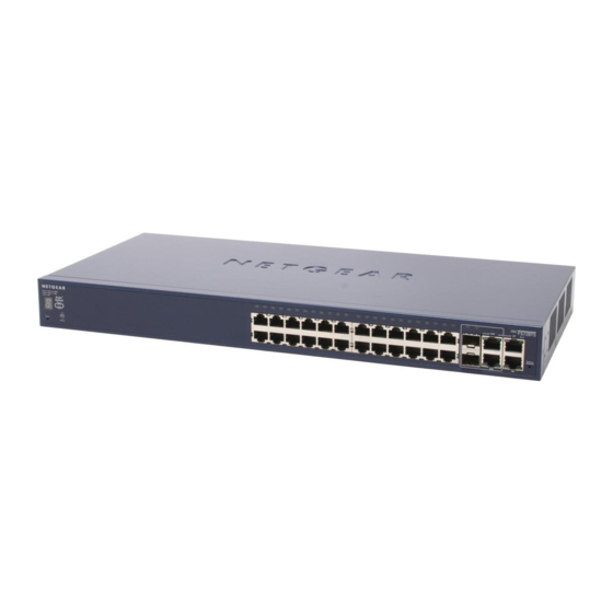
If any item is missing or damaged, contact the place of purchase immediately. Panel Layout Guide FS728TS Front Panel The NETGEAR FS728TS Smart Switch is a 24-Port 10/100M Stackable Smart Switch with 4 Gigabit Ports. Each RJ45 port automatically senses the line speed and negotiates duplex mode operation with the link partner. -
Page 18: Fs752Ts Front Panel
Hardware Installation Guide for the Prosafe Stackable Smart Switch FS700TS Series FS752TS Front Panel The NETGEAR FS752TS Smart Switch is a 48-Port 10/100M Stackable Smart Switch with 4 Gigabit Ports. Each RJ45 port automatically senses the line speed and negotiates duplex mode operation with the link partner. -
Page 19: Fs752Tps Front Panel
Hardware Installation Guide for the Prosafe Stackable Smart Switch FS700TS Series FS752TPS Front Panel The NETGEAR FS752TPS Smart Switch is a 48-Port 10/100M and PoE Stackable Smart Switch with 4 Gigabit Ports. Each RJ45 port automatically senses the line speed and negotiates duplex mode operation with the link partner. -
Page 20: Led Designations
Hardware Installation Guide for the Prosafe Stackable Smart Switch FS700TS Series LED Designations Port LEDs The following table describes the port LED designations. Table 1. Port LEDs Non-POE Device Table 2-1. PORT LEDs on Non-PoE Devices Port 24/48 10/100M Ports—One... - Page 21 Hardware Installation Guide for the Prosafe Stackable Smart Switch FS700TS Series Table 2-2. Port LEDS on PoE Devices Port 48 10/100M Ports—One Link/ACT/SPD LED LED/Port (Ethernet Mode) 24 10/100M Ports—One POE Indicate LED/ LED/Port (PoE Mode) POE fault 4 Gigabit Copper Ports—...
-
Page 22: Front Panel Buttons
The last saved configuration will be loaded onto the switch as it resets. The LEDs on the switch should go out and then come back on as the switch goes through its Power On Switch Test (POST). -
Page 23: Device Hardware Interfaces
The GBIC module bays accommodate standard SFP GBIC modules, such as the AGM731F, AGM732F, or AGM733 from NETGEAR, allowing fiber connections on the network. The module bay is a combo port, sharing a connection with an RJ-45 port. Being a combo port, only one type of connection can be active at any given time. - Page 24 Hardware Installation Guide for the Prosafe Stackable Smart Switch FS700TS Series 2-14 Introduction v1.0, December 2005...
-
Page 25: Chapter 3 Installation
This chapter describes the installation procedures for your NETGEAR Smart Switch. Switch installation involves the following steps: Step 1: Preparing the site Step 2: Installing the switch Step 3: Checking the installation Step 4: Connecting devices to the switch Step 5: Installing an SFP GBIC module... -
Page 26: Step 2: Installing The Switch
Step 2: Installing the Switch The NETGEAR Smart Switch can be installed on a flat surface or in a standard 19-inch rack. Installing the Switch on a Flat Surface The switch ships with four self-adhesive rubber footpads. Stick one rubber footpad on each of the four concave spaces on the bottom of the switch. -
Page 27: Step 3: Checking The Installation
Hardware Installation Guide for the Prosafe Stackable Smart Switch FS700TS Series 5. Tighten the screws with a #2 Phillips screwdriver to secure the switch in the rack. Figure 3-1 Step 3: Checking the Installation Before applying power check the following: 1. -
Page 28: Step 4: Connecting Devices To The Switch
NETGEAR Smart Switch contains Auto Uplink™ technology, which allows the attaching of devices using either straight-through or crossover cables. Connect each PC to an RJ-45 network port on the Switch front panel, as shown in the diagram below. Use Category 5 (Cat5) unshielded twisted-pair (UTP) cable terminated with an RJ-45 connector to make these connections. -
Page 29: Step 5: Installing An Sfp Gbic Module
The default port for connecting the devices in a stack is the Gigabit copper port. The fiber port can also be used for stacking. Enabling the fiber port to be used for stacking, is through the switch's web page once the device has been booted and is operational. - Page 30 Master and slave designations are configured through automatic discovery. Manually changing the stacking configuration is through switch's web page once the device has been booted and is operational. For more information on stacking see the NETGEAR Prosafe Stackable Smart Switch User Guide. Installation v1.0, December 2005...
-
Page 31: Step 7: Applying Ac Power
Hardware Installation Guide for the Prosafe Stackable Smart Switch FS700TS Series Step 7: Applying AC Power NETGEAR Smart Switch does not have an ON/OFF switch. The method of applying or removing AC power is by connecting or disconnecting the power cord. Before connecting the power cord, select an AC outlet that is not controlled by a wall switch, which can turn off power to the switch. - Page 32 Hardware Installation Guide for the Prosafe Stackable Smart Switch FS700TS Series Installation v1.0, December 2005...
-
Page 33: Troubleshooting
This chapter provides information about troubleshooting the NETGEAR Smart Switch. Topics include the following: • Troubleshooting chart • Additional troubleshooting suggestions Troubleshooting Chart The following table lists symptoms, causes, and solutions of possible problems. Table 4-1. Troubleshooting Chart Symptom Cause Power LED is off. -
Page 34: Additional Troubleshooting Suggestions
AC power from the switch and then reapply AC power. If the problem continues, contact NETGEAR technical support. In North America, call 1-888-NETGEAR. If you are outside of North America, please refer to the support information card included with your product. -
Page 35: Auto-Negotiation
The RJ-45 ports negotiate the correct duplex mode and speed if the device at the other end of the link supports auto negotiation. If the device does not support auto negotiation, the switch only determines the speed correctly and the duplex mode defaults to half-duplex. - Page 36 Hardware Installation Guide for the Prosafe Stackable Smart Switch FS700TS Series Troubleshooting v1.0, December 2005...
-
Page 37: Technical Specifications
LEDs Performance Specifications: Forwarding modes: Bandwidth: Address database size: Mean Time Between Failure (MTBF): 100,000 hours (~11 years) for FS728TS; 84,000 hours (~ 9.5 years) Technical Specifications Technical Specifications IEEE 802.3ab 1000BASE-T IEEE 802.3ad IEEE 802.3af Power over Ethernet (FS752TPS only) IEEE 802.3z 1000Base-X... - Page 38 43.2 mm x 440 mm x 205 mm FS752TPS: 1.7" x 17.32" x 10.12" 43.2 mm x 440 mm x 257 mm FS728TS: 5.73 lbs, FS752TS: 6.57 lbs, FS752TPS: 8.92 lbs FS728TS: 2.6 kg, FS752TS: 2.98 kg FS752TPS: 4.05 kg 0° to 50° C (32º...
- Page 39 Hardware Installation Guide for the Prosafe Stackable Smart Switch FS700TS Series Technical Specifications v1.0, December 2005...
- Page 40 Hardware Installation Guide for the Prosafe Stackable Smart Switch FS700TS Series Technical Specifications v1.0, December 2005...
-
Page 41: Appendix B Related Documents
This appendix provides links to reference documents you can use to gain a more complete understanding of the technologies used in your NETGEAR product. Document Internet Networking and TCP/IP Addressing Wireless Communications Preparing a Computer for Network Access Virtual Private Networking (VPN) - Page 42 Hardware Installation Guide for the Prosafe Stackable Smart Switch FS700TS Series Related Documents v1.0, December 2005...
Need help?
Do you have a question about the FS728TS and is the answer not in the manual?
Questions and answers