
Related Manuals for Samsung AM FNCD Series


Summary of Contents for Samsung AM FNCD Series
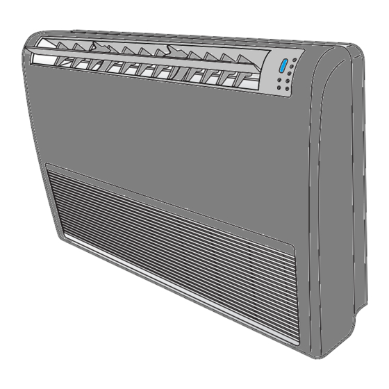
- Page 1 Convertible Type Series Ceiling/Floor:AM✴✴✴FNCD✴✴✴ Air Conditioner installation manual imagine the possibilities Thank you for purchasing this Samsung product. EN TR RU UK KK IN FR AR DB68-03880A-05...
-
Page 2: Table Of Contents
X This manual explains how to install an indoor unit with a split system with two SAMSUNG units. The use of other types of units with different control systems may damage the units and invalidate the warranty. The manufacturer shall not be responsible for damages arising from the use of non compliant units. - Page 3 X Do not attempt to repair, move, alter or reinstall the unit. If performed by unauthorized personnel, these operations may cause electric shocks or fires. X Do not place containers with liquids or other objects on the unit. X All the materials used for the manufacture and packaging of the air conditioner are recyclable. X The packing material and exhaust batteries of the remote control(optional) must be disposed of in accordance with current laws.
-
Page 4: Accessories
Safety Precautions • Make sure that you earth the cables. CAUTION Do not connect the earth wire to the gas pipe, water pipe, lighting rod or telephone wire. If earthing is not complete, electric shock or fire may occur. • Install the circuit breaker. If the circuit breaker is not installed, electric shock or fire may occur. -
Page 5: Selecting The Installation Location
Selecting the installation location Indoor Unit • Select a convenient location that permits the air to reach every corner of the area to be cooled. • Pre-plan for easy and short routing of the refrigerant tubing and wiring to the outdoor unit. • There should be no flammable gas, alkaline, substances present in the air. - Page 6 Selecting the installation location AM✴✴✴FNCD✴✴✴ (Unit : mm) 1000 Back side Pipe outlet-(bottom side) P ip e o u tle t (b o tto m s id e ) Air intake hole(Ø50) A ir in ta k e h o le ( 5 0 ) Wiring hole W irin g h o le Drain hose outlet...
-
Page 7: Ceiling Installation
Ceiling installation It is recommended to install theY-joint before installing the indoor unit. 1. Select pipe directions. When the directions are selected, drill 3-1/8’’-(100mm, for pipe and cables) and 1-3/4’’-(40mm, for drain hose) diameter holes on the wall 300mm or 300mm or so that it slants slightly downwards toward the outdoor for smooth more... -
Page 8: Floor Installation
Floor installation 1. Select pipe directions. 300mm or When the directions are selected, drill 3-1/8’’ (100mm, for pipe and more cables) and 1-3/4’’ (40mm, for drain hose) diameter holes on the wall so that it slants slightly downwards toward the outdoor for smooth water flow. -
Page 9: Eev Kit Installation
EEV Kit installation Preparing for Installation 1. Check dimension and installation location. Concrete 2. Check installation place. Insert • By using a pattern sheet, check required installation space. Hole in anchor Hole in plug Suspension bolt(3/8" or M10)-field supply (Unit : mm) 450mm X 200mm or more (Maintenance Hole) Maintenance hole must be located on... - Page 10 EEV Kit installation Connection of refrigerant piping & Insulation 1. Insert bot anchors, use existing ceiling supports or construct a suitable support. • Ensure the ceiling is strong enough to support the weight of the indoor unit. Before hanging the unit, test the CAUTION strength of each attached suspension bolt.
- Page 11 Wiring & Assigning address Room A Room B Another EEV Kit Outdoor unit 1. Connect the AC power cable and communication cable from the outdoor unit to terminal, then connect the cable to another EEV kit. 2. Connect the AC power cable and communication cable to each indoor unit (A, B and C). 3.
-
Page 12: Purging The Unit
EEV Kit installation KEY function • If you press a KEY on the PCB, the display will show you a step of appropriate EEV Kit. KEY No. Meaning Example Step of EEV Kit A Step of EEV Kit B 19 (19 x 10 = 190 STEP) Step of EEV Kit C Test run • Each indoor unit runs separately to check pipe connection and address setting. -
Page 13: Connecting The Refrigerant Pipe
Connecting the refrigerant pipe There are two refrigerant pipes of differing diameters: • A smaller one for the liquid refrigerant • A larger one for the gas refrigerant • The inside of copper pipe must be clean & has no dust. 1. -
Page 14: Cutting/Flaring The Pipes
Cutting/Flaring the Pipes 1. Make sure that you prepared the required tools. (pipe cutter, reamer, flaring tool and pipe holder) 2. If you want to shorten the pipe, cut it using a pipe cutter ensuring that the cut edge remains at 90° with the side of the pipe. There are some examples of correctly and incorrectly cut edges below. - Page 15 5. Check if you flared the pipe correctly. There are some examples of incorrectly flared pipes below. Correct Inclined Damaged Surface Cracked Uneven Thickness 6. Align the pipes and tighten the flare nuts first manually and then with a torque wrench, applying the following torque. Connection Torque Flare Outer diameter...
-
Page 16: Performing Leak Test & Insulation
Performing leak test & insulation Leak test LEAK TEST WITH NITROGEN (before opening valves) In order to detect basic refrigerant leaks, before recreating the vacuum and recirculating the R410A, it’s responsible of installer to pressurize the whole system with nitrogen (using a pressure regulator) at a pressure above 4.1MPa (gauge). - Page 17 5. Select the insulation of the refrigerant pipe. • Insulate the gas side and liquid side pipe referring to the thickness according to the pipe size. • Indoor temperature of 30°C and humidity of 85% is the standard condition. If install in a high humidity condition,use one grade thicker insulator by referring to the table below. If installing in an unfavorable conditions, use thicker one.
-
Page 18: Drain Hose Installation
Drain hose installation Care must be taken when installing the drain hose for the indoor unit to ensure that any condensation water is correctly drained outside. When passing the drain hose through the hole drilled in the wall, check that none of the following situations occur. -
Page 19: Wiring Work
Wiring Work Power and communication cable connection 1. Before wiring work, you must turn off all power source. 2. Indoor unit power should be supplied through the breaker( ELCB or MCCB+ELB ) separated by the outdoor power. ELCB:Earth Leakage Circuit Breaker MCCB:Molded Case Circuit Breaker ELB:Earth Leakage Breaker 3. - Page 20 Wiring Work Specification of electronic wire Power supply MCCB ELB or ELCB Power cable Earth cable Communication cable Max : 242V XA, 30mmA 2.5mm 2.5mm 0.75~1.5mm Min : 198V 0.1 s • Decide the capacity of ELCB(or MCCB+ELB) by below formula. • Power supply cords of parts of appliances for outdoor use shall not be lighter than polychloroprene sheathed flexible cord.
- Page 21 Example of Installation Total power cable length L = 100(m), Running current of each units 1[A] Total 10 indoor units were installed 9[A] 1[A] 10[A] ELCB or MCCB+ Indoor unit1 Indoor unit2 Indoor unit10 0[m] 10[m] 20[m] 100[m] • Apply following equation. Coef×35.6×L ×i 10% of input...
- Page 22 Wiring Work • Select the power cable in accordance with relevant local and national regulations. • Wire size must comply with local and national code. CAUTION • For the power cable, use the grade of H07RN-F or H05RN-F materials. • You should connect the power cable into the power cable terminal and fasten it with a clamp. • The unbalanced power must be maintained within 10% of supply rating among whole indoor units.
-
Page 23: Setting An Indoor Unit Address And Installation Option
Setting an indoor unit address and installation option Set the indoor unit address and installation option with remote controller option. Set the each option separately since you cannot set the ADDRESS setting and indoor unit installation setting option at the same time. You need to set twice when setting indoor unit address and installation option. The procedure of option setting Air flow direction (Up and down) Adusts the air flow direction up and down... - Page 24 Setting an indoor unit address and installation option Option setting Status 1. Setting SEG2, SEG3 option Press Low Fan button( ) to enter SEG2 value. Press High Fan button( ) to enter SEG3 value. Each time you press the button, … will be selected in rotation. SEG2 SEG3 2.
- Page 25 Option setting Status 12. Setting Cool mode Press Mode button to be change to Cool mode in the OFF status. 13. Setting SEG16, SEG17 option Press Low Fan button( ) to enter SEG16 value. Press High Fan button( ) to enter SEG17 value. Each time you press the button, ...
- Page 26 Setting an indoor unit address and installation option Setting an indoor unit address (MAIN/RMC) 1. Check whether power is supplied or not. When the indoor unit is not plugged in, there should be additional Indoor Unit power supply in the indoor unit. 1(L) 2.
- Page 27 Setting an indoor unit installation option (suitable for the condition of each installation location) 1. Check whether power is supplied or not. When the indoor unit is not plugged in, there should be additional Indoor Unit power supply in the indoor unit. 1(L) 2.
- Page 28 Setting an indoor unit address and installation option The output of hot water heater in SEG9 is generated from the hot coil part of the terminal board in duct models. * The output of hot coil terminal is AC 220 V / 230 V (The same as Indoor Unit’s input Power) 1(L) 2(N) COM1...
- Page 29 Option SEG13 SEG14 SEG15 SEG16 SEG17 SEG18 Use of external Setting the output of external control / Explanation PAGE S-Plasma ion Buzzer control Hours of filter usage control External heater On/Off signal Remote Controller Display Details Setting the External Indication Details Indication Details Indication Indication Details Indication...
- Page 30 Setting an indoor unit address and installation option Advanced function: Controlling cooling/heating current or power saving with motion detect. Minimizing fan operation when thermostat is off (*1) - Fan operates for 20 seconds at an interval of 5 minutes in heat mode. (*2) 1: Fan is turned on continually when the hot water heater is turned on, 3: Fan is turned off when the hot water heater is turned on with cooling only indoor unit...
- Page 31 05 series installation option(Detailed) Option No. : 05XXXX-1XXXXX-2XXXXX-3XXXXX Option SEG1 SEG2 SEG3 SEG4 SEG5 SEG6 (When setting SEG3) (When setting SEG3) (When setting SEG3) Use of Auto Change Standard for mode Explanation PAGE MODE Over for HR only in Standard heating temp. Standard cooling change Auto mode...
- Page 32 Setting an indoor unit address and installation option (*3) Option SEG13 SEG14 SEG15 SEG16 SEG17 SEG18 Explanation Control variables when using hot water / external heater Remote Controller Display Details Indication Set temp. for heater On/Off Delay time for heater On At the same time as thermo on No delay At the same time as thermo on...
- Page 33 SEG 3, 4, 5, 6, 8, 9 additional information When the SEG 3 is set as “1” and follow Auto Change Over for HR only operation, it will operate as follows. Standard temp. for Temp. Heating Cooling Standard temp. for Cooling Set temp.
- Page 34 Setting an indoor unit address and installation option Changing a particular option You can change each digit of set option. Option SEG1 SEG2 SEG3 SEG4 SEG5 SEG6 The tens’ digit of an The unit digit of an The option mode Explanation PAGE MODE...
-
Page 35: Final Checks And User Tips
Final Checks and User Tips To complete the installation, perform the following checks and tests to ensure that the air conditioner operates correctly. Check the followings. • Strength of the installation site • Tightness of pipe connection to detect a gas leak • Electric wiring connections • Heat-resistant insulation of the pipe • Drainage... -
Page 36: Troubleshooting
Troubleshooting Detection of errors • If an error occurs during the operation, an LED flickers and the operation is stopped except the LED. • If you re-operate the air conditioner, it operates normally at first, then detect an error again. LED Display on the receiver &... - Page 37 LED Display Abnormal condition Error code 1. COND mid sensor is detached E241 2. Refrigerant leakage (2nd detection) E554 3. Abnomally high temperature on Cond (2nd detection) E450 4. Low pressure s/w (2nd detection) E451 5. Abnomally high temperature on discharged air on outdoor unit (2nd E416 detection) 6.
-
Page 38: How To Connect Your Extended Power Cables
How to connect your extended power cables 1. Prepare a compressor and the following tools. Connection sleeve Tools Crimping pliers Insulation tape Contraction tube (mm) (mm) Spec MH-14 20xØ6.5(HxOD) Width 19mm 70xØ8.0(LxOD) Shape 2. As shown in the figure, peel off the shields from the rubber or wire of the Power cable (provided by us) power cable. - Page 39 5. Wrap it with the insulation tape twice or more and position your contraction tube in the middle of the insulation tape. A total of three or more layers of insulation is required. f Method 1 f Method 2 Insulation tape Insulation tape 40 mm 35 mm...
Need help?
Do you have a question about the AM FNCD Series and is the answer not in the manual?
Questions and answers