Advertisement
Quick Links
Advertisement

Related Manuals for Bosch FPE-7039


Summary of Contents for Bosch FPE-7039
- Page 1 MUX expansion module FPE-7039 Installation manual en english es-AR español pt-BR português...
- Page 3 MUX expansion module en english Notices es-AR español Avisos pt-BR português Avisos Bosch Security Systems. Inc. 2016.10 | 1.0 | F.01U.330.684...
- Page 4 | Notices MUX expansion module Notices These instructions cover the installation of the FPE-7039 Multiplex Expansion Module in a fire system supervised by an FPD‑7024 Fire Alarm Control Panel (FACP). Open Source Software information Notice! For general information regarding open source software in Bosch Security Systems please visit http:// www.boschsecurity.com/oss...
- Page 5 MUX expansion module Notices | en Bosch Security Systems. Inc. 2016.10 | 1.0 | F.01U.330.684...
- Page 6 | Notices MUX expansion module 2016.10 | 1.0 | F.01U.330.684 Bosch Security Systems. Inc.
- Page 7 MUX expansion module Notices | en Bosch Security Systems. Inc. 2016.10 | 1.0 | F.01U.330.684...
- Page 8 | Notices MUX expansion module 2016.10 | 1.0 | F.01U.330.684 Bosch Security Systems. Inc.
- Page 9 MUX expansion module Notices | en Bosch Security Systems. Inc. 2016.10 | 1.0 | F.01U.330.684...
- Page 10 NFPA codes, local codes, and the authority having jurisdiction (AHJ). Failure to follow these instructions can result in failure of a detector to initiate an alarm event. Bosch Security Systems, Inc. is not responsible for improperly installed, tested or maintained devices.
- Page 11 100 system users (an addition of 84 PINs from the base system). The module can be programmed remotely from a PC using RPS Remote programming software. The module can be used with the Bosch Security Systems, Inc. control panels and modules indicated in the following table. Control panels Active:...
- Page 12 D7053 Multiplex Input-output module FLM-7024-ISO MUX bus isolator module FMM-7045 Multiplex addressable manual pull station FMM-7045-D dual-action multiplex addressable manual pull station * Legacy products were investigated to comply only to UL864 8th edition 2016.10 | 1.0 | F.01U.330.684 Bosch Security Systems. Inc.
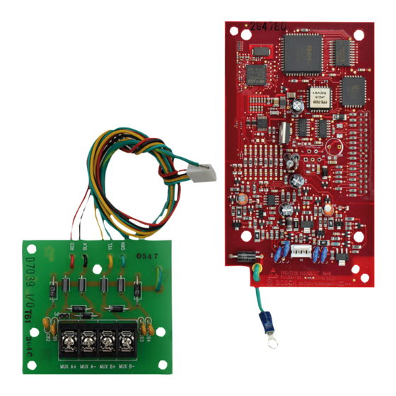
- Page 13 Static-sensitive components! The FACP and modules contain static‑sensitive components and must be handled with care. Follow proper antistatic handling procedures. FPE-7039 board mounting Figure 3.1: Mounting the FPE-7039 1 FPE-7039 2 FACP 3 Mounting holes (4) for 4 FACP connector pins...
- Page 14 Install the FACP in the enclosure. Use the mounting screw (callout 5 above) to secure the FPE‑7039’s ground wire (callout 6 above) to the FACP. I/O module mounting Figure 3.2: Mounting the FPE-7039 I/O module 1 FACP enclosure 2 FPE-7039 I/O module 3 Plastic standoffs (3)
- Page 15 I/O module to the FACP ground terminal If the FPE-7039 board is not mounted to the FACP board, mount it using the instructions above. Insert the three plastic standoffs (see callout 3 in the above figure) in the mounting holes in the enclosure.
- Page 16 Check the intersection point of the capacitance and number of devices on the second chart below. If the data point falls in the light area, your choices are acceptable. If not, see the Notice above. 2016.10 | 1.0 | F.01U.330.684 Bosch Security Systems. Inc.
- Page 17 Wire length 5950 ft. (1810 m), depends on wire size and number of devices Wire <0.12 μF (maximum per bus), depends on capacitance* wire size and number of devices Bosch Security Systems. Inc. 2016.10 | 1.0 | F.01U.330.684...
- Page 18 9 Class B branch (addresses 9 to 128) All MUX terminals are power-limited and supervised Ensure the loop is disconnected from the FPE‑7039 Module. Measure loop resistance by shorting: the end of the farthest device in Class B. 2016.10 | 1.0 | F.01U.330.684 Bosch Security Systems. Inc.
- Page 19 Figure 4.2: Measuring Class B loop resistance 1 50 Ω maximum 2 MUX bus wires 3 Clip lead Figure 4.3: Measuring Class A loop resistance 1 50 Ω maximum 2 MUX bus wires 3 Clip lead Bosch Security Systems. Inc. 2016.10 | 1.0 | F.01U.330.684...
-
Page 20: Specifications
Current Draw Alarm 190 mA maximum Load, Class A 100 mA maximum Load, Class B 100 mA maximum for each bus Standby 190 mA maximum Bus Voltage 8.5 V to 13 V Wire Resistance (maximum) 50 Ω Class A or Class B 2016.10 | 1.0 | F.01U.330.684 Bosch Security Systems. Inc.
Need help?
Do you have a question about the FPE-7039 and is the answer not in the manual?
Questions and answers