
Related Manuals for Bosch FM441/CMM 910


Summary of Contents for Bosch FM441/CMM 910
- Page 1 Mounting Instructions Modules for control units CSM 7x0, CFB 8x0 and CFB 9x0 FM441/CMM 910 FM455/CMC 900 FM442/CMM 920 FM457/CMC 920 FM443/CMS 910 FM458/CMC 930 FM444/CMG 910 FM448/CMB 900-0-10V...
-
Page 2: Table Of Contents
Introduction ........3 Definition of the various modules . -
Page 3: Introduction
Introduction | 3 Introduction These mounting instructions explain installation of the function modules CMx in the control unit series CSM 7x0, CFB 8x0 and CFB 9x0. USER INFORMATION Generally, these installation instructions can also be used for installing other modules, as the procedure is similar. Definition of the various modules Definitions CM = Controller module... -
Page 4: Modules And Their Designation
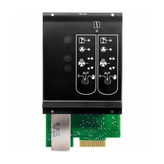
ZM433 1 heating circuit Burner + boiler circuit functions + ZM434 0 - 10 % burner control ZM425 Display module FM441/CMM 910 1 heating circuit + 1 DHW circuit FM442/CMM 920 2 heating circuits FM443/CMS 910 Solar circuit FM444/CMG 910... -
Page 5: Safety
You may request the declaration of conformity for the product. See rear page for contact details of your local branch or from the relevant Bosch Thermotechnology branch. 6 720 803 029 (2011/08) Modules for control units CSM 7x0, CFB 8x0 and CFB 9x0... -
Page 6: Explanation Of The Symbols Used
6 | Safety Explanation of the symbols used Two levels of danger are identified and signalled by the following terms: RISK OF FATAL INJURY Identifies possible risks associated with a product that might lead to serious injury or even death if appropriate care is not taken. WARNING! RISK OF INJURY / SYSTEM DAMAGE Identifies potentially dangerous situations, which might lead to... -
Page 7: Disposal
USER INFORMATION Only use original replacement parts from Bosch Thermotechnology. Bosch Thermotechnology cannot take responsibility for losses caused by the use of parts not supplied by Bosch Thermotechniology. Disposal Electronic components must not be disposed of with general domestic waste. -
Page 8: Module Assembly For Control Units Csm 7X0
This section describes the installation of the function modules CMx in the control units CSM 710 and CSM 750. USER INFORMATION Check that all parts have been delivered. If this is not the case, contact a Bosch Thermotechnology branch. Possible module installations for control units CSM 7x0 CMS 7x0 Designation... -
Page 9: Arrangement Of The Modules In The Control Unit (Csm 7X0)
Module assembly for control units CSM 7x0 | 9 Arrangement of the modules in the control unit (CSM 7x0) Fig 1 Slot assignment Slot 1 Slot 2 Slot B behind the programming unit Slot A for function module FM455/CMC 900 (only for CSM 750) ZM424 and FM455/CMC 900 (only for CSM 750) The module FM455/CMC 900 always occupies slot A ( Fig. -
Page 10: Fitting
10 | Module assembly for control units CSM 7x0 Fitting Fig 2 Removing covers RISK OF FATAL INJURY due to electrical current when the control unit is open. Before opening the control unit: WARNING! Isolate all poles of the power supply and secure against unintentional reconnection. - Page 11 Module assembly for control units CSM 7x0 | 11 Fig 3 Pivoting down device front Press in upper nubs ( Fig. 3, [1] and [2]) on both sides. Fold out forwards the device front with the Programmer ( Fig. 3, [3]). USER INFORMATION Ensure that the cable cover has been removed, otherwise you will not be able to pivot the device front forward.
- Page 12 12 | Module assembly for control units CSM 7x0 Fig 4 Removing the cross brace You will need a screwdriver to remove the crossbar ( Fig. 4, [1]). Undo the crossbar on one side. For this push one of the two clips Fig.
- Page 13 Module assembly for control units CSM 7x0 | 13 Fig 5 Removing blanking plate When fitting a new module Remove blanking plate from slot 1 ( Fig. 5) in the control unit. Connection cables for sensors and pumps must be laid and provided with terminals before installation of the module (more detailed information can be found in the technical documentation for control units CSM 7x0).
- Page 14 14 | Module assembly for control units CSM 7x0 Fig 6 Inserting a module When removing and replacing a module Disconnect leads for the respective module and fix in standby position (more detailed information can be found in the mounting instructions for control units CSM 7x0).
- Page 15 Module assembly for control units CSM 7x0 | 15 Fig 7 Connect power supply to slot 1 Connecting module power supply to slot 1 Plug in sensor leads and pump connections at the designated points on the module. Plug 230 V module connector into the correct position in the terminal strip ( Fig.
- Page 16 16 | Module assembly for control units CSM 7x0 Fig 8 Connecting power to slot 2 Connecting module power supply to slot 2 Remove dummy plug ( Fig. 8, [1]) of the three-pole plug (cable loom). Plug in 230 V module connecting plug to the three-pole plug Fig.
- Page 17 Module assembly for control units CSM 7x0 | 17 Fig 9 Positioning crossbar After module installation Position crossbar ( Fig. 9, [1]) in the recesses and click into place. Pivot the device front ( Fig. 9, [2]) back and click into place. 6 720 803 029 (2011/08) Modules for control units CSM 7x0, CFB 8x0 and CFB 9x0...
- Page 18 18 | Module assembly for control units CSM 7x0 Fig 10 Fitting casing cover and cable cover Position top casing cover. Replace both screws on the upper housing cover ( Fig. 10, [1] and [2]). If additional cables were routed out of the device, the cable cover may need to be cut out in the lower section.
-
Page 19: Removing And Replacing The Function Module Fm455/Cmc 900 (Only For Csm 750)
Module assembly for control units CSM 7x0 | 19 Removing and replacing the function module FM455/CMC 900 (only for CSM 750) Fig 11 Replacing the module FM455/ CMC 900 If it is necessary to replace the FM455/CMC 900 module, first remove the ZM424 module from slot 1. - Page 20 20 | Module assembly for control units CSM 7x0 Jumper switch The jumper switch is used to configure the module: Function Position open The module logs on as a new (factory module FM455/CMC 900 or setting) FM457/CMC 920. USER INFORMATION The jumper switch must be open if EMS is in use.
-
Page 21: Module Mounting For Control Unit Cfb 840
This section describes the installation of the function modules CMx in the control unit CFB 840. USER INFORMATION Check that all parts have been delivered. If this is not the case, contact a Bosch Thermotechnology branch. Possible module installations for control unit CFB 840 Designation CFB 840... -
Page 22: Arrangement Of Modules In The Control Unit
22 | Module mounting for control unit CFB 840 Arrangement of modules in the control unit Fig 13 Slot assignment Slot 1 for an additional module Slot 2 for an additional module Slot B behind the Programmer programming unit Slot A for central module ZM422 (standard version) USER INFORMATION Slot A ( Fig. -
Page 23: Fitting
Module mounting for control unit CFB 840 | 23 Fitting Fig 14 Removing covers Screws Terminal cover RISK OF FATAL INJURY due to electrical current when the control unit is open. Before opening the control unit: Isolate all poles of the power supply and secure against WARNING! unintentional reconnection. - Page 24 24 | Module mounting for control unit CFB 840 Fig 15 Module installation and removal When fitting a new module Remove blanking plate in control unit. Connection cables for sensors or pumps must be routedand provided with terminals before installation of the module (more detailed information can be found in the technical documentation for control units CFB 840).
- Page 25 Module mounting for control unit CFB 840 | 25 When removing and replacing a module Disconnect leads for the respective module and fix in standby position (more detailed information can be found in the mounting instructions for control units CFB 840). Pull module out of the control unit.
- Page 26 26 | Module mounting for control unit CFB 840 USER INFORMATION The connector clips are locked to prevent slippage. When removing the terminals press the locking tab upwards. Position terminal cover and secure with the screws. Test the module function. More detailed information can be found in the operating and servicing instructions for control unit CFB 840.
-
Page 27: Module Assembly For Control Units Cfb 9X0
This section describes as a priority the installation of the function modules CMx in the control units CFB 9x0. USER INFORMATION Check that all parts have been delivered. If this is not the case, contact a Bosch Thermotechnology branch. Possible module installations for control units CFB 9x0 CFB 9x0 Designation... -
Page 28: Arrangement Of Modules In The Control Unit
28 | Module assembly for control units CFB 9x0 USER INFORMATION The modules FM448/CMB 900-0-10V and FM458/CMC 930 must never be inserted in the same control unit. If you install both modules (FM448/CMB 900-0-10V and FM458/ CMC 930), this leads to an error message on the Programmer display. USER INFORMATION The modules FM457/CMC 920 and FM458/CMC 930 must never be inserted in the same control unit. - Page 29 (slot 1-4). Example (with the help of the CFB 930) Heating circuit allocation for two heating circuit modules (FM442/ CMM 920) and one heating circuit and DHW module (FM441/CMM 910): Fig 18 Example of the function module arrangement...
-
Page 30: Fitting
30 | Module assembly for control units CFB 9x0 Fitting Fig 19 Removing covers RISK OF FATAL INJURY due to electrical current when the control unit is open. Before opening the control unit: WARNING! Isolate all poles of the power supply and secure against unintentional reconnection. - Page 31 Module assembly for control units CFB 9x0 | 31 Fig 20 Module installation and removal When fitting a new module Remove blanking plate from slot 1 ( Fig. 20) in the control unit. Connection cables for sensors aor pumps must be routed and provided with terminals before installation of the module (more detailed information can be found in the technical documentation for control units CFB 9x0).
- Page 32 32 | Module assembly for control units CFB 9x0 When removing and replacing a module Disconnect leads for the respective module and fix in standby position (more detailed information can be found in the mounting instructions for control units CFB 9x0). Pull module out of the control unit.
- Page 33 Module assembly for control units CFB 9x0 | 33 Position terminal cover and secure with the screws. Test the module function. More detailed information can be found in the operating and servicing instructions for control units CFB 9x0. USER INFORMATION If there is no 230 V power supply for the module or one of its 230 V components (e.g.
- Page 34 34 | Module assembly for control units CFB 9x0 Notes 6 720 803 029 (2011/08) Modules for control units CSM 7x0, CFB 8x0 and CFB 9x0...
- Page 35 Module assembly for control units CFB 9x0 | 35 Notes 6 720 803 029 (2011/08) Modules for control units CSM 7x0, CFB 8x0 and CFB 9x0...
- Page 36 Clayton, VIC 3168 Phone 1300 30 70 37 Fax 1300 30 70 38 www.bosch.com.au/hotwater New Zealand Phone 0800 4 Bosch or 08 543 352 www.bosch.co.nz C & F Quadrant Ltd. Unit L40 Cherry Orchard Industrial Estate Cherry Orchard, Dublin 10 Tel.: 01.6305700...
Need help?
Do you have a question about the FM441/CMM 910 and is the answer not in the manual?
Questions and answers