Table of Contents
Advertisement
Quick Links
Advertisement
Table of Contents
Troubleshooting

Related Manuals for CU Medical Systems Paramedic AED Series


Summary of Contents for CU Medical Systems Paramedic AED Series
- Page 1 Emergency Responder 3 CU – ER3 Operator’s Manual CU Medical Systems, Inc.
- Page 2 CU-ER3 Operator’s Manual _ver 2.00 Paramedic CU-ER3 Quick Reference Card...
- Page 3 CU-ER3 Operator’s Manual _ver 2.00 Notice Paramedic CU-ER3 Operator’s Manual CU Medical Systems, Inc. reserves the right to make changes on the device specifications contained in this manual at any time without prior notice or obligation to customers. Printed in the Republic of Korea Publication Date: April 2006 Operator’s Manual Part No.: CU-ER3 version 2.00...
-
Page 4: Table Of Contents
CU-ER3 Operator’s Manual _ver 2.00 TABLE OF CONTENTS Table Of Contents ................4 General ..................8 Warranty ..................9 Warranty Disclaimer ............... 9 Service ..................10 Contact Us ...................11 1 How to Use This Manual ............12 1.1 Contents of This Manual ...........12 1.2 Manual Conventions............12 2 Device Operation Guidelines ............13 2.1 General Guidelines............13... - Page 5 CU-ER3 Operator’s Manual _ver 2.00 4.5.7 Administration Device Setup ........50 4.5.7.1 AED Settings ..........52 4.5.7.2 General Settings ........54 4.5.7.3 Password ..........56 4.5.8 Device Setup, Monitor ...........59 4.5.9 Printing and Transferring Data ........63 4.5.10 Return ...............65 4.5.11 Speaker Volume Adjustment.........65 5 Device Setup and Storage ............66 5.1 Unpacking ..............66 5.2 Setup................66 5.2.1 Manual Self-Test ...........66...
- Page 6 CU-ER3 Operator’s Manual _ver 2.00 10 SPO2 Monitoring..............889 10.1 Overview ..............889 10.2 Pulse Oximetry Sensors ..........90 10.3 Application and Connection of the Sensor ......91 10.4 SPO2 Monitoring............91 10.5 Setting the Alarm ............93 10.6 Responding to an Alarm ..........93 10.7 SPO2 Monitoring Notes and Warnings.......94 11 Power Supply .................96 11.1 Power Sources ..............96...
- Page 7 CU-ER3 Operator’s Manual _ver 2.00 APPENDIX D................133 Technical Specifications ............133 Electromagnetic Compatibility..........143...
-
Page 8: General
Please read this Operator’s Manual carefully and thoroughly before using the Paramedic CU-ER3 to be fully acquainted with its operating and maintenance instructions. CU Medical Systems, Inc. designs and manufactures all of its products in accordance with international standards (NS-EN ISO9001:2000/ ISO13485:2003-MDD 93/42/EEC). This ensures that CU Medical Systems, Inc. -
Page 9: Warranty
This warranty does not apply if the product has been damaged by accident or misuse or as the result of service or modification by an entity other than CU Medical Systems, Inc. or its authorized representatives. IN NO EVENT SHALL CU MEDICAL SYSTEMS, INC. -
Page 10: Service
CU-ER3 Operator’s Manual _ver 2.00 ◐ Service The Paramedic CU-ER3 must be serviced only by authorized personnel. Unauthorized servicing during the warranty period renders the warranty null and void. The Paramedic CU-ER3 will be serviced free of charge during the warranty period. After the warranty period, the cost of material and service shall be shouldered by the user. -
Page 11: Contact Us
Fax: +82 33 747 7659 email address: service@cu911.com Our website: http://www.cu911.com EU Authorized Representative of CU Medical Systems, Inc. A.M.I Italia s.r.l Via Cupa Reginella N 17A 80010 Quarto (Napoli) Italy Tel No 0039 (0) 81 806 34 75 0039 (0) 81 806 34 75... -
Page 12: How To Use This Manual
CU-ER3 Operator’s Manual _ver 2.00 1 How to Use This Manual 1.1 Contents of This Manual This Operator’s Manual contains all the information a user needs to operate the Paramedic CU-ER3 properly. In case you have any problems regarding the operation of the device, please don’t hesitate to contact the manufacturer. -
Page 13: Device Operation Guidelines
CU-ER3 Operator’s Manual _ver 2.00 2 Device Operation Guidelines 2.1 General Guidelines Do not operate or store the device in conditions that are beyond the following specified limits. Operating Conditions Temperature 32 °F to 104 °F (0 °C to 40 °C) Humidity 5 % to 95 % (non-condensing) Standby conditions (Stored with defibrillator electrode pads, ready... -
Page 14: Electrical Safety Guidelines
Do not use the Paramedic CU-ER3 if it has been submerged in water. Call immediately for service assistance. To ensure safety and reliability, use only parts and accessories approved by CU Medical Systems, Inc. 2.2 Electrical Safety Guidelines Use the correct power supply during recharging. See the Chapter on Power Supply for more details. -
Page 15: Introduction
The Paramedic CU-ER3 may also be used to do ECG monitoring only when it is in Manual mode. ECG monitoring only is done by connecting the custom designed ECG monitoring cable assembly from CU Medical Systems, Inc. No shocks may be delivered when the ECG monitoring cable assembly is connected to the Paramedic CU-ER3. -
Page 16: Indicated Use
CU-ER3 Operator’s Manual _ver 2.00 3.2 Indicated Use 3.2.1 AED Mode In AED Mode, the Paramedic CU-ER3 is indicated for use on patients that are exhibiting the symptoms of sudden cardiac arrest (SCA). The Paramedic CU-ER3 is to be used on patients that are suspected of suffering from sudden cardiac arrest with all of the following signs: a) Unresponsiveness b) Absence of normal breathing... -
Page 17: Spo2 Monitoring
CU-ER3 Operator’s Manual _ver 2.00 3.2.3 SPO2 Monitoring Indications: • SPO2 Monitoring is indicated when it is beneficial to assess a patient’s oxygen saturation level. Contraindications • There are no known contraindications for SPO2 Monitoring. 3.2.4 ECG Monitoring Indications: • ECG Monitoring is indicated when it is desired to monitor the heart rate of a patient. -
Page 18: Intended Users
CU-ER3 Operator’s Manual _ver 2.00 3.3 Intended Users The Paramedic CU-ER3 is intended for use by emergency rescue organizations. 3.3.1 AED Mode In AED Mode, the Paramedic CU-ER3 is intended for use by emergency rescue personnel who have been trained in basic life support that includes the use of AEDs 3.3.2 Manual Mode In Manual Mode, the Paramedic CU-ER3 is intended for use by health care professionals and emergency rescue personnel who have been trained in advanced cardiac life support. -
Page 19: Operating Controls, Indicators And Accessories
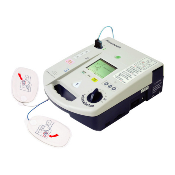
CU-ER3 Operator’s Manual _ver 2.00 4 Operating Controls, Indicators and Accessories 4.1 Device Parts Illustration Figure 4-1. Top view of the Paramedic CU-ER3... - Page 20 CU-ER3 Operator’s Manual _ver 2.00 Figure 4-2 Side view of the Paramedic CU-ER3...
- Page 21 CU-ER3 Operator’s Manual _ver 2.00 Device Parts Explanation Displays the ECG and plethysmographic waveform of the LCD Screen patient and the various prompts and indicators. Microphone Captures audio signals during a rescue operation. Plays voice prompts during rescue operation and recorded Speaker audio signal during recording playback.
- Page 22 CU-ER3 Operator’s Manual _ver 2.00 Device Parts Explanation, continued Operating Controls, continued Used to initiate charging of the defibrillating capacitor or to make the Paramedic CU-ER3 begin analysis of the patient’s ECG. CHARGE/ANALYZE Used to synchronize the delivery of the shock with the R- Wave of the patient’s ECG.
- Page 23 CU-ER3 Operator’s Manual _ver 2.00 Device Parts Explanation, continued Input/Output Ports Used to connect the Defibrillator Electrode Pads assembly to the Paramedic CU-ER3. ECG-DEFIB port Also used to connect the custom made ECG MONITORING CABLE AND CONNECTOR ASSEMBLY to the Paramedic CU-ER3. SmartMedia Receptacle for the SmartMedia card.
-
Page 24: Accessories
CU-ER3 Operator’s Manual _ver 2.00 4.2 Accessories Only parts and accessories approved by CU Medical Systems, Inc. must be used with the Paramedic CU-ER3. Using parts and accessories that are not approved by CU Medical Systems, Inc. may degrade performance. - Page 25 CU-ER3 Operator’s Manual _ver 2.00 Standard Accessories Self adhesive, pre-gelled defibrillator electrode pads used to acquire the ECG signal from the patient and to deliver the defibrillation shock to the patient. Defibrillator Electrode Pads and Connector Assembly A reference card that enumerates the steps to be done during a rescue operation.
- Page 26 CU-ER3 Operator’s Manual _ver 2.00 Optional Accessories The cable and connector assembly that must be used if it is desired to run the Paramedic CU-ER3 in ECG monitoring mode. ECG Monitoring Cable and Connector Assembly Used for the ECG Monitoring Cable and Connector Assembly ECG Monitoring Electrodes The defibrillator electrode pads that must be used...
- Page 27 CU-ER3 Operator’s Manual _ver 2.00 Optional Accessories, continued A stand-alone thermal printer that enables you to print the ECG and rescue data stored in the internal and removable flash memories of the Paramedic CU-ER3 Thermal Printer Used to connect the device to a car cigar lighter jack for recharging the batteries.
- Page 28 CU-ER3 Operator’s Manual _ver 2.00 Optional Accessories, continued Used to store the Paramedic CU-ER3 and the accessories needed for a rescue operation. Carrying Case...
-
Page 29: Screen Display Views
CU-ER3 Operator’s Manual _ver 2.00 4.3 Screen Display Views 4.3.1 Initial Screen Display AED Mode Turn on the Paramedic CU-ER3 while the MODE/ENERGY SELECTOR is set to AED ON and observe the initial screen display shown on Figure 4-3. This screen is shown right after the Paramedic CU-ER3 is done with its Power-On Self-Test (Power-On Self-Test is indicated by a text prompt “STARTING UP”). - Page 30 CU-ER3 Operator’s Manual _ver 2.00 Initial Screen Display Legend Flashing pads Indicate the location where the defibrillator electrode pads must be icon placed Battery Level Indicator: Power provided by the internal battery pack Shows the charge status of the battery pack of the Paramedic CU-ER3 The battery is fully charged Battery level is 80% of full charge Battery level is 65% of full charge...
- Page 31 CU-ER3 Operator’s Manual _ver 2.00 Initial Screen Display Legend, continued: Indicates actions that you need to do (in AED Mode) or indicates the Text Prompt state of the sensors (in Manual Mode) SYNC Indicates that the shock delivery will be synchronized with the R-wave Indicator of the patient - indicates the heart rate of the patient, in beats per minute (BPM).
-
Page 32: Screen Display; Rescue Operation Ongoing
CU-ER3 Operator’s Manual _ver 2.00 4.3.2 Screen Display; Rescue Operation Ongoing AED Mode Heart Rate Shock Count Alarm Status Indicator Energy SPO2 Value Heart Rate Calculation Source Indicator ECG Display Chest Compression : Breath ratio indicator Elapsed Battery Level Time Indicator Text Prompt Manual Mode... -
Page 33: Voice And Text Prompts
CU-ER3 Operator’s Manual _ver 2.00 4.4 Voice and Text Prompts These voice and text prompts are given when the device is operated in AED mode except for the following: • The “ECG MONITORING MODE” text prompt is given only when the device is in Manual Mode and the ECG monitoring cable assembly is connected to the ECG- DEFIB port of the device. - Page 34 CU-ER3 Operator’s Manual _ver 2.00 Voice and Text Prompts, continued These voice and text prompts are given when the device is operated in AED mode except for the following: • The “ECG MONITORING MODE” text prompt is given only when the device is in Manual Mode and the ECG monitoring cable assembly is connected to the ECG- DEFIB port of the device.
-
Page 35: Menu Operation
CU-ER3 Operator’s Manual _ver 2.00 4.5 Menu Operation Enter Menu Operation by selecting MENU in the MODE SELECTOR KNOB before turning the device ON. Upon entering Menu Operation, the Paramedic CU-ER3 displays the following screen: DEVICE INFORMATION DEVICE HISTORY BATTERY HISTORY RETURN To navigate through the menu, use the UP, MENU, and DOWN buttons on the keypad of the device. -
Page 36: Device History
CU-ER3 Operator’s Manual _ver 2.00 4.5.1 Device History Device History contains the history of the device during its lifetime. The following data are displayed on the LCD: number and total elapsed time of device usage number of shocks delivered number and total elapsed time of trainings conducted using the device number and total elapsed time of the different tests (daily, weekly, monthly, and manual tests) To access Device History turn ON the device with the MODE SELECTOR set to MENU and... - Page 37 CU-ER3 Operator’s Manual _ver 2.00 In this example the Device History indicates the following: Uses Middle Number of times the Paramedic CU-ER3 was used in RESCUE column operations. In this example, the Paramedic CU-ER3 was used 15 times in rescue operations. A rescue operation is counted when the following conditions occur: The Paramedic CU-ER3 is turned ON.
-
Page 38: Battery History
CU-ER3 Operator’s Manual _ver 2.00 4.5.2 Battery History The battery history indicates the number of minutes that the battery has been in use and the current state of the battery (GOOD or LOW). To access Battery History turn ON the device with the MODE SELECTOR set to MENU and press the sequence of keypad buttons shown in the following table. - Page 39 CU-ER3 Operator’s Manual _ver 2.00 Battery History, continued Press the following button(s) The Paramedic CU-ER3 displays the following in sequence: screen(s) in sequence: BATTERY HISTORY USAGE TIME 43500 Menu Button GOOD STATUS PRESS THE MENU KEY TO RETURN Battery History indicates the following: USAGE TIME Total time that the internal battery pack is used as the power supply of the Paramedic CU-ER3.
-
Page 40: Usage Review
CU-ER3 Operator’s Manual _ver 2.00 4.5.3 USAGE REVIEW USAGE REVIEW displays the list of Rescue Events recorded together with their time stamp. The list of Rescue Events is given in the following table. Name of Event Event Power ON Indicates the time when the Paramedic CU-ER3 is turned ON. Power OFF Indicates the time when the Paramedic CU-ER3 is turned OFF Indicates the time when the defibrillator electrode pads are... - Page 41 CU-ER3 Operator’s Manual _ver 2.00 To access Usage Review turn ON the device with the MODE SELECTOR set to MENU and press the sequence of keypad buttons shown in the following table. Press the following button(s) The Paramedic CU-ER3 displays the following in sequence: screen(s) in sequence: DEVICE INFORMATION...
- Page 42 CU-ER3 Operator’s Manual _ver 2.00 Usage Review, continued Press the following button(s) The Paramedic CU-ER3 displays the following in sequence: screen(s) in sequence: USAGE REVIEW 7 Sep 2003 22:00 ELAPSED TIME 00:03:22 Menu Button TOTAL SHOCKS DETAILED REVIEW RETURN USAGE REVIEW POWER ON 00:00:00 PADS ON...
-
Page 43: Ecg Review
CU-ER3 Operator’s Manual _ver 2.00 4.5.4 ECG REVIEW ECG REVIEW • Displays the ECG record stored in the internal memory or the SmartMedia Card memory. • ECG data from the latest rescue operation can be scrolled to the right or to the left (earlier or later part of the recording, respectively). - Page 44 CU-ER3 Operator’s Manual _ver 2.00 ECG Review, continued Press the following button(s) The Paramedic CU-ER3 displays the following in sequence: screen(s) in sequence: REVIEW INCIDENT USAGE REVIEW ECG REVIEW Down Button VOICE REVIEW RETURN ECG REVIEW Menu Button 1 / 13 PRESS THE MENU KEY TO RETURN...
-
Page 45: Voice Review
CU-ER3 Operator’s Manual _ver 2.00 4.5.5 VOICE REVIEW VOICE REVIEW • Plays back the voice recorded during a rescue operation • Works only if the SmartMedia Card is inserted (Voice record can be stored only in the SmartMedia Card). To access Voice Review, turn ON the device with the MODE SELECTOR set to MENU and press the sequence of keypad buttons shown in the following table. - Page 46 CU-ER3 Operator’s Manual _ver 2.00 Voice Review, continued Press the following button(s) The Paramedic CU-ER3 displays the following in sequence: screen(s) in sequence: REVIEW INCIDENT USAGE REVIEW ECG REVIEW Down Button VOICE REVIEW RETURN REVIEW INCIDENT USAGE REVIEW ECG REVIEW Down Button VOICE REVIEW RETURN...
-
Page 47: General Device Setup
CU-ER3 Operator’s Manual _ver 2.00 4.5.6 GENERAL DEVICE SETUP GENERAL DEVICE SETUP • enables you to change or adjust operating parameters such as date, time, and voice recording To access General Device Setup, turn ON the device with the MODE SELECTOR set to MENU and press the sequence of keypad buttons shown in the following table. - Page 48 CU-ER3 Operator’s Manual _ver 2.00 General Device Setup, continued Press the following button(s) The Paramedic CU-ER3 displays the following in sequence: screen(s) in sequence: DEVICE SETUP GENERAL ADMINISTRATION Menu Button MONITOR RETURN GENERAL DATE 03 / 09 / 09 TIME 00:15 Menu Button VOICE REC.
- Page 49 CU-ER3 Operator’s Manual _ver 2.00 General Device Setup, continued The parameter variables are highlighted one by one by pressing the MENU button while the parameter is highlighted. For example, when DATE is highlighted, the day, month, or year can be highlighted by pressing the MENU button repeatedly until the desired variable is reached.
-
Page 50: Administration Device Setup
CU-ER3 Operator’s Manual _ver 2.00 4.5.7 ADMINISTRATION DEVICE SETUP In the DEVICE SETUP, ADMINISTRATION, operating parameters such as automatic reanalysis in AED mode, ECG Gain, and speaker volume can be set or adjusted by the operator. To access Device Setup, Administration, turn ON the device with the MODE SELECTOR set to MENU and press the sequence of keypad buttons shown in the following table. - Page 51 CU-ER3 Operator’s Manual _ver 2.00 Device Setup, Administration, continued Press the following button(s) The Paramedic CU-ER3 displays the following in sequence: screen(s) in sequence: DEVICE SETUP GENERAL ADMINISTRATION Menu Button MONITOR RETURN DEVICE SETUP GENERAL ADMINISTRATION DOWN Button MONITOR RETURN PASSWORD Enter Password __ __ __ __...
-
Page 52: Aed Settings
CU-ER3 Operator’s Manual _ver 2.00 4.5.7.1 AED SETTINGS The AED Settings Menu allows you to turn the Reanalysis option ON or OFF. To access the AED Settings, access the Device Setup, Administration Menu by pressing the keypad keys as shown in 4.5.7 Press the following button(s) The Paramedic CU-ER3 displays the following in sequence:... - Page 53 CU-ER3 Operator’s Manual _ver 2.00 Setting the Automatic Reanalysis Option ON makes the Paramedic CU-ER3 analyze and reanalyze the ECG signal from the patient during operation in AED mode without intervention from you. When this option is turned OFF, you have to press the ANALYZE/CHARGE button to initiate ECG signal analysis.
-
Page 54: General Settings
CU-ER3 Operator’s Manual _ver 2.00 4.5.7.2 GENERAL SETTINGS The General Settings menu enables you to set the ECG gain and the volume of the speaker. To access the General Settings Menu, access the Device Setup, Administration Menu by pressing the keypad keys as shown in 4.5.7 Press the following button(s) The Paramedic CU-ER3 displays the following in sequence:... - Page 55 CU-ER3 Operator’s Manual _ver 2.00 You may scroll the highlighter between ECG GAIN and Volume by pressing the UP or DOWN key button. You may change the ECG GAIN or Volume setting by pressing the Menu button while ECG GAIN or Volume is highlighted, respectively. When the parameter variable is highlighted, change its value by pressing the UP or DOWN button.
-
Page 56: Password
CU-ER3 Operator’s Manual _ver 2.00 4.5.7.3 Password The Password Menu enables you to change the password for the Manual Mode and to set the Manual Mode Security ON or OFF. Setting the Manual Mode Security ON makes the device ask for the Password before you can operate it in Manual Mode. - Page 57 CU-ER3 Operator’s Manual _ver 2.00 Password Menu, continued Press the following button(s) The Paramedic CU-ER3 displays the following in sequence: screen(s) in sequence: ADMINISTRATION AED SETTINGS GENERAL SETTINGS Down Button PASSWORD RETURN PASSWORD Enter New Password __ __ __ __ Menu Button Manual Mode Security PASSWORD...
- Page 58 CU-ER3 Operator’s Manual _ver 2.00 Password Menu, continued Press the following button(s) The Paramedic CU-ER3 displays the following in sequence: screen(s) in sequence: PASSWORD Enter New Password Either UP button or DOWN button to set the Manual Mode Manual Mode Security Security OFF or ON PASSWORD Enter New Password...
-
Page 59: Device Setup, Monitor
CU-ER3 Operator’s Manual _ver 2.00 4.5.8 Device Setup, Monitor The Device Setup, Monitor Menu enables you to set the Monitor Settings of the Paramedic CU-ER3. You may set the alarm function together with its limits in this menu. You may also set the display on the screen. - Page 60 CU-ER3 Operator’s Manual _ver 2.00 Device Setup, Monitor, continued Press the following button(s) The Paramedic CU-ER3 displays the following in sequence: screen(s) in sequence: DEVICE SETUP GENERAL ADMINISTRATION Menu Button MONITOR RETURN DEVICE SETUP GENERAL ADMINISTRATION DOWN Button MONITOR RETURN DEVICE SETUP GENERAL ADMINISTRATION...
- Page 61 CU-ER3 Operator’s Manual _ver 2.00 Device Setup, Monitor, continued Cycle through the parameters by pressing the UP or DOWN button. To change the value of a parameter, highlight its variable by pressing the Menu button while the parameter is highlighted and then press the UP or DOWN button. For example, when HR Limits is highlighted, the lower limit or the upper limit can be highlighted by pressing the MENU button repeatedly until the desired variable is reached.
- Page 62 CU-ER3 Operator’s Manual _ver 2.00 Shortcut Access to the Device Setup, Monitor Menu In Manual Mode, fast access to the Device Setup, Monitor Menu is provided through the keys of the Menu Keypad. ALARM and the rate limits can be set by pressing the Menu Button. A window pops up on the screen when the Menu Button is pressed while the Paramedic CU-ER3 is operating in Manual Mode.
-
Page 63: Printing And Transferring Data
CU-ER3 Operator’s Manual _ver 2.00 4.5.9 Printing and Transferring Data The ECG and rescue data stored in the internal flash memory or the SmartMedia Card may be printed through the optional stand-alone thermal printer or transferred to a personal computer. If the SmartMedia Card is not inserted, the data stored in the internal flash memory is printed. - Page 64 CU-ER3 Operator’s Manual _ver 2.00 Communication-Print, continued Press the following button(s) The Paramedic CU-ER3 displays the following in sequence: screen(s) in sequence: DEVICE SETUP GENERAL ADMINISTRATION DOWN Button MONITOR RETURN COMMUNICATION DATA TRANSMISSION DATA RECEPTION DOWN Button PRINT RETURN COMMUNICATION DATA TRANSMISSION DATA RECEPTION MENU Button...
-
Page 65: Return
CU-ER3 Operator’s Manual _ver 2.00 Press the following button(s) The Paramedic CU-ER3 displays the following in sequence: screen(s) in sequence: COMMUNICATION DATA TRANSMISSION DATA RECEPTION DOWN Button PRINT RETURN The data transmission and printing processes are discussed thoroughly in Chapter 14 – Data Management and Review. -
Page 66: Device Setup And Storage
CU-ER3 Operator’s Manual _ver 2.00 5 Device Setup and Storage 5.1 Unpacking • Carefully inspect the packing container and the device for any damage that might have been sustained during shipping. • Check the shipping list to ensure that the unit comes with the complete accessories. It is important to have all the necessary accessories all the time. -
Page 67: Battery Charge Check
CU-ER3 Operator’s Manual _ver 2.00 5.2.2 Battery Charge Check The internal battery pack of the Paramedic CU-ER3 is fully charged before leaving the factory. In the course of storage in the distribution system, the battery pack may be depleted when the Paramedic CU-ER3 reaches you. The Manual Self-Test in the previous section can detect a drained battery pack condition. -
Page 68: Storage
CU-ER3 Operator’s Manual _ver 2.00 Monitor Settings The Paramedic CU-ER3 enables you to set the following monitor settings: Alarm HR Limits SpO2 Limits DISPLAY To set the Monitor Settings, see section 4.5.8 5.3 Storage Place the Paramedic CU-ER3 in an accessible place so that it can be used readily during emergencies. -
Page 69: Defibrillating In Aed Mode
CU-ER3 Operator’s Manual _ver 2.00 6 Defibrillating in AED Mode 6.1 Overview In AED mode, the Paramedic CU-ER3 determines whether the patient needs a defibrillation shock or not. Defibrillation is achieved in three easy steps after the patient is connected to the Paramedic CU-ER3. -
Page 70: Aed Automatic Reanalysis Mode
CU-ER3 Operator’s Manual _ver 2.00 6.2 AED Automatic Reanalysis Mode The Paramedic CU-ER3 will be operating in Automatic Reanalysis Mode if it has been set for automatic reanalysis (see section 4.5.7.1) Insert the SmartMedia Card into port (optional) Select AED ON on the mode selector knob Turn the Paramedic CU-ER3 ON If patient is:... -
Page 71: Preparation
CU-ER3 Operator’s Manual _ver 2.00 6.2.1 Preparation 1. Insert SmartMedia Card if desired. 2. Turn the MODE/ENERGY Selector Knob to AED ON. 3. Turn ON the Paramedic CU-ER3 4. Evaluate the condition of the patient. The patient must exhibit the symptoms indicated for AED defibrillation. - Page 72 CU-ER3 Operator’s Manual _ver 2.00 CHILD DEFIBRILLATION If you are going to use the Pediatric Electrode Pads, you must set the Paramedic CU-ER3 to output 150 Joules by selecting AED ON or Manual ON with energy set to 150 Joules. Do not use the Reduced-energy Pediatric Electrode Pads with an output setting other than 150 Joules.
-
Page 73: Step 3: Ecg Acquisition And Analysis
CU-ER3 Operator’s Manual _ver 2.00 Always make sure that the defibrillator electrode pads stored together with the Paramedic CU-ER3 are in good condition and not yet past their expiration date. See the reverse side of the defibrillator electrode pads for their placement guide. - Page 74 CU-ER3 Operator’s Manual _ver 2.00 If the decision is SHOCK ADVISED: 1. The Paramedic CU-ER3 charges itself in preparation for shock delivery. • The Paramedic CU-ER3 emits a warning tone during charging. • The Paramedic CU-ER3 gives the text prompt “CHARGING COMPLETE”...
-
Page 75: Step 3 Shock Delivery
CU-ER3 Operator’s Manual _ver 2.00 6.2.3 Step 3 Shock Delivery Press the SHOCK Button if instructed. • You must press the SHOCK button when the Paramedic CU-ER3 gives the prompt to press the flashing red SHOCK button in order to deliver the shock. •... - Page 76 CU-ER3 Operator’s Manual _ver 2.00 The patient should be kept motionless during signal acquisition and analysis. If the patient is being transported in an emergency vehicle, the vehicle should be stopped during ECG signal acquisition and analysis. Attach the pad as described on the reverse side of the defibrillator pads. Make sure that there is good contact between the defibrillator pads and the patient’s skin.
-
Page 77: Cardiopulmonary Resuscitation (Cpr)
CU-ER3 Operator’s Manual _ver 2.00 6.2.4 Cardiopulmonary Resuscitation (CPR) After delivery of a shock, the Paramedic CU-ER3 pauses to enable you to administer CPR to the patient. Check the patient for signs of circulation after delivering a shock. In the absence of circulation, administer 5 cycles of cardiopulmonary resuscitation (CPR). -
Page 78: Aed No Automatic Reanalysis Mode
CU-ER3 Operator’s Manual _ver 2.00 6.3 AED NO Automatic Reanalysis Mode The Paramedic CU-ER3 is in NO Automatic Reanalysis Mode if it has been set for NO automatic reanalysis (see section 4.5.7.1) Insert the SmartMedia Card into port (optional) Select AED ON on the mode selector knob Turn the Paramedic CU-ER3 ON If patient is:... - Page 79 CU-ER3 Operator’s Manual _ver 2.00 Rescue Operation in NO Automatic Reanalysis Mode The Rescue Protocol in NO Automatic Reanalysis Mode is similar to the Rescue Protocol in Automatic Reanalysis Mode except for the following differences: • You must press the ANALYZE button in order for the Paramedic CU-ER3 to begin analysis of the patient’s ECG.
-
Page 80: Asynchronous Defibrillation In Manual Mode
CU-ER3 Operator’s Manual _ver 2.00 7 Asynchronous Defibrillation in Manual Mode 7.1 Overview In MANUAL mode, you have to determine whether the patient needs defibrillation or not. You will also have to set the energy level of the shock to be delivered. Manual Mode Defibrillation is achieved in three steps after the patient is connected to the Paramedic CU-ER3. - Page 81 CU-ER3 Operator’s Manual _ver 2.00 Asynchronous Manual Defibrillation Flowchart...
-
Page 82: Patient Preparation
CU-ER3 Operator’s Manual _ver 2.00 7.2 Patient Preparation 1. Insert SmartMedia Card if desired. 2. Turn the MODE/ENERGY Selector Knob to MANUAL ON. Select the energy setting that is appropriate for the patient. 3. Turn ON the Paramedic CU-ER3. 4. Evaluate the condition of the patient. The patient must exhibit the symptoms indicated for Asynchronous Manual Defibrillation. -
Page 83: Analysis
CU-ER3 Operator’s Manual _ver 2.00 7.3 ANALYSIS Analyze the ECG of the patient and decide whether the patient needs a defibrillation shock or not. 7.4 CHARGING If the patient needs a defibrillation shock, press the CHARGE button when it is active as shown in the following figure. -
Page 84: Shock
CU-ER3 Operator’s Manual _ver 2.00 7.5 SHOCK Confirm that the patient still needs a defibrillation shock. Confirm that the Paramedic CU-ER3 has finished charging. The beeper must emit a continuous tone and the SHOCK button must be flashing its red backlight. Make sure that nobody is touching the patient and shout out loudly “STAND CLEAR!”... -
Page 85: Synchronized Cardioversion
CU-ER3 Operator’s Manual _ver 2.00 8 Synchronized Cardioversion 8.1 OVERVIEW The Paramedic CU-ER3 may be used to treat patients with Atrial Fibrillation through synchronized cardioversion. Synchronized cardioversion enables you to deliver the shock synchronized with the R-wave of the patient. The ECG monitored during Synchronized Cardioversion is acquired using the same defibrillator electrode pads that are used to deliver the synchronized shock. -
Page 86: Shock
CU-ER3 Operator’s Manual _ver 2.00 8.6 SHOCK Confirm that the patient still needs a synchronized cardioversion shock. Confirm that the Paramedic CU-ER3 has finished charging. The beeper must emit a continuous tone and the SHOCK button must be flashing its red backlight. Make sure that nobody is touching the patient and shout out loudly “STAND CLEAR!”... -
Page 87: Ecg Monitoring In Manual Mode
9.1 ECG Monitoring Mode You may activate the ECG Monitoring Mode by connecting the custom-made ECG Monitoring Cable and Connector Assembly provided by CU Medical Systems, Inc. In this mode, the Paramedic CU-ER3 does not do any arrhythmia analysis. Only the ECG and the calculated heart rate of the patient are shown on the screen display. - Page 88 Do not attempt to operate the Paramedic CU-ER3 in ECG MONITORING MODE using cable and connector assemblies other than the proper cable and connector assembly supplied by CU Medical Systems, Inc. During ECG MONITORING MODE, the Paramedic CU-ER3 does not do any analysis of the ECG waveform.
-
Page 89: Spo2 Monitoring
CU-ER3 Operator’s Manual _ver 2.00 10 SPO2 Monitoring 10.1 Overview The Paramedic CU-ER3 is fitted with a Nellcor SPO2 Module. The SPO2 Module measures functional oxygen saturation in the blood. The measurement determines the oxygenated hemoglobin as a percentage of the hemoglobin that can transport oxygen. -
Page 90: Pulse Oximetry Sensors
CU-ER3 Operator’s Manual _ver 2.00 10.2 Pulse Oximetry Sensors The Paramedic CU-ER3 is equipped with a DS100A reusable Nellcor sensor that is designed to be used with a finger of the patient. Other sensors from Nellcor may also be used with the Paramedic CU-ER3. The following table shows all the Nellcor Oximetry sensors that may be used with the Paramedic CU-ER3. -
Page 91: Application And Connection Of The Sensor
CU-ER3 Operator’s Manual _ver 2.00 10.3 Application and Connection of the Sensor Apply the sensor to the site specified in the table in section 10.2 Connect the sensor cable to the SPO2 Sensor Port as shown in the following figure: As soon as the SPO2 Cable is connected, the Paramedic CU-ER3 acquires the SPO2 signal of the patient. - Page 92 CU-ER3 Operator’s Manual _ver 2.00 In Manual Mode The SPO2 value is displayed on the screen at the upper right hand corner. The plethysmographic wave of the patient may be displayed on the screen by pressing the UP button on the Menu keypad. The UP button toggles the display of the plethysmographic wave ON and OFF.
-
Page 93: Setting The Alarm
CU-ER3 Operator’s Manual _ver 2.00 10.5 Setting the Alarm The SPO2 alarm may be set to warn you if the SPO2 value goes outside of the defined lower and upper limits. The alarm may be set by accessing the Device Setup, Monitor Menu. See section 4.5.8 If the SPO2 value falls outside the specified limits, an alarm tone alerts you of the said condition. -
Page 94: Spo2 Monitoring Notes And Warnings
CU-ER3 Operator’s Manual _ver 2.00 10.7 SPO2 Monitoring Notes and Warnings • The SPO2 module in the Paramedic CU-ER3 measures functional oxygen saturation – oxygenated hemoglobin expressed as a percentage of the hemoglobin that can transport oxygen. • The range of the peak wavelengths and maximum optical power are stated in the Specifications found in the Appendices of this Operator’s Manual. - Page 95 CU-ER3 Operator’s Manual _ver 2.00 Physiological conditions, medical procedures, or external agents that may interfere with the monitor’s ability to detect and display measurements include dysfunctional hemoglobin, arterial dyes, low perfusion, dark pigment and externally applied coloring agents, such as nail polish, dye, or pigmented cream.
-
Page 96: Power Supply
CU-ER3 Operator’s Manual _ver 2.00 11 Power Supply 11.1 Power Sources The Paramedic CU-ER3 may be powered by the following power sources Internal Battery Pack External Battery Pack AC/DC Adapter (mains powered) Car Cigar Lighter Jack 11.2 Internal Battery Pack The default power supply of the Paramedic CU-ER3 is its internal battery pack, which is made of rechargeable Nickel Metal Hydride cells. - Page 97 CU-ER3 Operator’s Manual _ver 2.00 After the low battery condition is detected, the Paramedic CU-ER3 turns the ERROR indicator light ON then OFF and emits a single beep every minute. When the Paramedic CU-ER3 is turned ON after a low battery condition is detected, it does the following: Display the text prompt “LOW BATTERY CODE:0001”.
- Page 98 CU-ER3 Operator’s Manual _ver 2.00 Internal Battery Charging Indicator The Paramedic CU-ER3 indicates that charging is in progress through the Battery Indicator lamp. When charging is in progress, the Battery Indicator lamp is red and flashing. When charging is finished, the Battery Indicator lamp is green and non-flashing. Do not remove or change the internal battery pack.
-
Page 99: External Battery Pack
11.3 External Battery Pack An optional disposable external LiMnO battery pack is available from CU Medical Systems, Inc. This battery pack has a capacity of 200 shocks (150J into 50 ) when used before the recommended usage date. The battery pack is shown in the following figure:... - Page 100 CU-ER3 Operator’s Manual _ver 2.00 External Battery Pack Status The energy level of the external battery pack is monitored by the Paramedic CU-ER3. The status of the external battery pack is indicated by the battery status icon which is displayed on the LCD screen during operation. See section 4.3 for the explanation of the battery status icon.
-
Page 101: Ac/Dc Adapter
CU-ER3 Operator’s Manual _ver 2.00 11.4 AC/DC Adapter The AC/DC Adapter is primarily used for recharging the internal battery pack. However, it may also be used to power the Paramedic CU-ER3 during rescue operations. It has medical device grade isolation properties (passes the requirements of EN 60601-1). The AC/DC Adapter and the power cord are shown in the following figures Output Jack Power Cord Receptacle... -
Page 102: Car Cigar Lighter Jack
CU-ER3 Operator’s Manual _ver 2.00 Connecting the AC/DC Adapter a. Connect the power cord to the adapter. b. Plug the power cord to the power mains. c. Connect the output jack of the adapter to the AC/DC port of the Paramedic CU-ER3. Do not connect or disconnect the AC adapter plug while the device is being used, the transients during power changeover in the middle of a rescue operation may cause some problems in the operation of the device. -
Page 103: Testing, Maintenance, And Troubleshooting
CU-ER3 Operator’s Manual _ver 2.00 12 TESTING, MAINTENANCE, AND TROUBLESHOOTING 12.1 Testing To ensure that the Paramedic CU-ER3 is always ready for any emergencies, self tests and interactive tests are performed by the device. If the ERROR LED is ON, consult the chapter on Troubleshooting. -
Page 104: Periodic Self-Tests
CU-ER3 Operator’s Manual _ver 2.00 12.1.3 Periodic Self-Tests When the Paramedic CU-ER3 is stored with a charged battery pack connected to it, it performs periodic self-tests to ensure that it is ready for use in emergencies. Three types of periodic self-tests are done. These are: a) Daily Periodic Self-Test –... -
Page 105: Manual Self-Test
CU-ER3 Operator’s Manual _ver 2.00 12.1.5 Manual Self-Test The Paramedic CU-ER3 can also run a manual self-test that requires your intervention. The manual mode test evaluates all functions tested in all the automated test modes (Power On Self-Test, Run Time Self-Test, Daily/Weekly/Monthly Periodic Self-Test,). To initiate a Manual Self-Test: Press the UP( ) and DOWN( ) keys in the MENU keypad simultaneously. - Page 106 CU-ER3 Operator’s Manual _ver 2.00 Maintenance Activities Frequency Activity Actions to be Taken Check the Paramedic CU-ER3 If a message that the battery is low for any error messages that is displayed, recharge the battery. Daily might have been generated other error messages,...
- Page 107 CU-ER3 Operator’s Manual _ver 2.00 MAINTENANCE CHECKLIST Paramedic CU-ER3 Serial Number: _______________ Location/Vehicle ID: ___________ Date Scheduled Frequency Paramedic CU-ER3: Clean, no signs of damage, free of excessive wear Supplies Available -2 sets of defibrillator electrode pads, undamaged, sealed, within expiration date -supplementary supplies (razor, scissors, gloves, gauze)
-
Page 108: Cleaning The Paramedic Cu-Er3
CU-ER3 Operator’s Manual _ver 2.00 12.3 Cleaning the Paramedic CU-ER3 After each use, clean the Paramedic CU-ER3 using a soft, damp cloth moistened with any of the following solvents: Soap and water 70% solution isopropyl alcohol Chlorine bleach and water mixture (30 ml bleach/liter of water) Ammonia-based cleaners Hydrogen peroxide Do not immerse any part of the Paramedic CU-ER3 in fluids. -
Page 109: Troubleshooting
CU-ER3 Operator’s Manual _ver 2.00 13 Troubleshooting 13.1 Self-Tests The Paramedic CU-ER3 executes automated and manual self-tests to verify the functionality of its major subsystems. The Paramedic CU-ER3 raises alarms if it detects a fault during those self-tests. It raises more alarms when it is turned ON after a fault is detected. - Page 110 CU-ER3 Operator’s Manual _ver 2.00 Self-Test Errors, continued Error Name Code Fault Remedial Action Capacitor charge Return to an authorized SYSTEM ERROR 0032 comparator failure service center for repair Return to an authorized SYSTEM ERROR 0064 ECG relay failure service center for repair Impedance Measurement Return to an authorized SYSTEM ERROR...
-
Page 111: Prompts During Rescue Operation
CU-ER3 Operator’s Manual _ver 2.00 13.2 Prompts During Rescue Operation If there are problems during a rescue operation that prevents the Paramedic CU-ER3 from successfully operating, the Paramedic CU-ER3 gives voice and text prompts to inform you of the problems. These prompts, together with the remedial actions are shown in the following table. -
Page 112: Data Management And Review
SmartMedia Flash Memory Card – this is the optional, removable, nonvolatile memory card available from CU Medical Systems, Inc. Audio signals may be stored here. This card is also erased during the start of a rescue operation if it is inserted in its port before the Paramedic CU-ER3 is turned ON. -
Page 113: Data Review Using The Paramedic Cu-Er3
Card is ready to record data when the Paramedic CU-ER3 is turned ON for use. Only SmartMedia Cards supplied by CU Medical Systems, Inc. are compatible with the Paramedic CU-ER3. Do not use any other kind of flash memory card. - Page 114 CU-ER3 Operator’s Manual _ver 2.00 Reviewing Data Using a SmartMedia Card After installing the SmartMedia Card, turn ON the Paramedic CU-ER3. Activate the menu by pressing the MENU button. Go to REVIEW INCIDENT. The following screen is displayed REVIEW INCIDENT USAGE REVIEW ECG REVIEW VOICE REVIEW...
-
Page 115: Data Transfer To Personal Computer
To keep data permanently, it must be transferred to a computer that is running the CU Expert ECG Data Management Software. The CU Expert is an optional data management software available from CU Medical Systems, Inc. Data transfer can be done through the IrDA port or the UART port of the Paramedic CU- ER3. - Page 116 CU-ER3 Operator’s Manual _ver 2.00 Transmit the data from the Paramedic CU-ER3 through the following steps: Open the CU Expert ECG Data Management Software in the host personal computer. Turn the Paramedic CU-ER3 ON with the MODE/ENERGY selector knob set to MENU. Go to the CU Expert and begin data reception by executing the instructions given in its User’s Manual.
-
Page 117: Uart Port
CU-ER3 Operator’s Manual _ver 2.00 The Connection icon shows the status of the connection of the Paramedic CU-ER3 with the PC during data transmission Meaning Icon Before the start of data transmission: A connection has not been made yet. At the end of data transmission: Data transfer has been finished. -
Page 118: Printing Using A Stand-Alone Serial Printer
CU-ER3 Operator’s Manual _ver 2.00 14.4 Printing Using a Stand-alone Serial Printer The UART port may also be used to transmit data to a stand-alone serial printer. Stand-alone Serial Thermal Printer The optional stand-alone printer is a serial printer configured to receive data using RS232 protocol. - Page 119 CU-ER3 Operator’s Manual _ver 2.00 Loading Paper into the Printer Open the paper compartment of the printer by pushing the locks inward simultaneously. When the locks are disengaged, pull the paper compartment lid upward. This is shown in the following figure. Place a roll of printer paper into the compartment.
- Page 120 CU-ER3 Operator’s Manual _ver 2.00 Printing Data From the Paramedic CU-ER3 Connect the UART Port connector of the printer to the Paramedic CU-ER3’s UART port. Do not connect any connector (defibrillator electrode pads assembly or ECG monitoring electrodes assembly connector) to the ECG-DEFIB port of the Paramedic CU-ER3.
- Page 121 CU-ER3 Operator’s Manual _ver 2.00 The Paramedic CU-ER3 displays the following figure during printing (PRINT ALL). PRINT ALL PRESS THE MENU KEY TO RETURN If it is desired to print only a segment of the stored ECG data, highlight PRINT SEGMENT, then press the MENU button.
- Page 122 CU-ER3 Operator’s Manual _ver 2.00 PRINT SEGMENT POWER ON 00:00:00 00:00:00 PADS ON 00:00:05 ANALYZING 00:00:09 SHOCK ADVISED 00:00:18 ARMED PRESS THE MENU KEY TO RETURN Press the MENU button to print the chosen segment. While the segment is being printed, the Paramedic CU-ER3 displays the PRINT SEGMENT screen.
- Page 123 CU-ER3 Operator’s Manual _ver 2.00 Notes...
-
Page 124: E~Cube Biphasic Technology
CU-ER3 Operator’s Manual _ver 2.00 APPENDIX A cube Biphasic Technology 1. What is Defibrillation? Sudden cardiac arrest (SCA) associated with ventricular fibrillation (VF) remains a leading cause of unexpected death in the Western world. It has been estimated that chances for survival from SCA decrease approximately 7% to 10% with each passing minute and that survival rates after 12 minutes are only 2% to 5%. - Page 125 CU-ER3 Operator’s Manual _ver 2.00 When the Defibrillation shock is delivered, current flow is affected by transthoracic impedance, the body’s resistance from electrode to heart. Impedance is dependent on the anatomy of the chest, skin surface, air in the chest, hair, fat and bone, as well as the size and location of the defibrillation electrodes.
- Page 126 CU-ER3 Operator’s Manual _ver 2.00 ◈ cube Biphasic technology: 1. makes it asy to compensate the shock waveform to match the patient’s impedance. 2. is more fficient than monophasic technology 3. delivers nough energy for restoring heart rhythm. ase in compensation of patient impedance variance. Through e-cube Biphasic technology, defibrillation shock delivery is controlled while taking into consideration...
- Page 127 CU-ER3 Operator’s Manual _ver 2.00 2. more fficient than monophasic waveform The electrical therapy delivered by transthoracic cardiac defibrillators has changed little since the introduction of direct-current defibrillation more than 30 years ago. Throughout this time, the industry-standard shock waveform external defibrillators been...
- Page 128 CU-ER3 Operator’s Manual _ver 2.00 Extensive animal and human data with implanted devices demonstrate that biphasic waveforms offer substantial reductions in defibrillation thresholds and produce less myocardial dysfunction than monophasic waveforms. [1], [2], [3], [4] The defibrillation efficacy of the 150-J biphasic waveform was superior to that of the 200-J to 360-J conventional escalating-energy monophasic waveforms for 115 patients who presented with VF.
- Page 129 CU-ER3 Operator’s Manual _ver 2.00 nough energy for restoring heart rhythm The Biphasic Truncated Exponential waveform uses lower energy than the Monophasic waveform. But the lower energy of biphasic shock is more efficient than high energy of the monophasic shock for defibrillation to restore heart rhythm. In a multicenter, randomized, controlled trial of 150J biphasic waveform compared with 200J and 360J monophasic waveforms done in humans, Schneider et al [5] showed that “the 150-J biphasic waveform defibrillated at higher rates, resulting in more patients who...
- Page 130 CU-ER3 Operator’s Manual _ver 2.00 REFERENCES Chapman PD, Vetter JW, Souza JJ, Wetherbee JN, Troup PJ. Comparison of monophasic with single and dual capacitor biphasic waveforms for nonthoracotomy canine internal defibrillation. J Am Coll Cardiol. 1989;14:242.5. Kavanagh KM, Tang ASL, Rollins DL, Smith WM, Ideker RE. Comparison of the internal defibrillation thresholds for monophasic and double and single capacitor biphasic waveforms.
-
Page 131: Rescue Protocol In Aed Mode (Automatic Reanalysis)
CU-ER3 Operator’s Manual _ver 1.00 APPENDIX B Rescue Protocol in AED Mode (Automatic Reanalysis Start You pressed the ON/OFF button to turn ON the Paramedic CU-ER3 Paramedic Voice and text prompts: CU-ER3 detects/decides: ATTACH PADS AED electrode pads attached? Voice and text prompts: DO NOT TOUCH THE PATIENT Voice and text prompts: ANALYZING HEART RHYTHM... -
Page 132: Parts And Accessories Number
CU-ER3 Operator’s Manual _ver 1.00 APPENDIX C Parts and Accessories Number To order replacement parts and accessories, please cite the part numbers given in the table below. Standard Parts Name Part Number Paramedic CU-ER3 2 sets of Multifunction Defibrillator Electrode Pads CUA0508O Power Cord AC/DC Adapter... - Page 133 CU-ER3 Operator’s Manual _ver 2.00 APPENDIX D TECHNICAL SPECIFICATIONS Physical Category Nominal Specifications Size 305 mm X 250 mm X 95 mm (L X W X H) Weight Approximately 2.8 kg Environmental Category Nominal Specifications 32 °F to 104 °F (0 °C to 40 °C) Temperature Operating Conditions...
- Page 134 CU-ER3 Operator’s Manual _ver 2.00 Arrhythmia Detector Performance ECG Analysis System - ECG Database Test 90% One Test Minimum test Performance Shock No Shock Observed Sided Lower Rhythm Rhythms sample sample size goal Decision Decision Performance Confidence size Class Limit 97.26% Coarse >90%...
- Page 135 CU-ER3 Operator’s Manual _ver 2.00 Defibrillator Category Nominal Specifications Operating Modes Manual / Semi automatic e e e e -cube biphasic (Truncated exponential type); impedance Waveform (Manual and AED Modes) compensated Shock Delivery Via multi-function defibrillator electrode pads Patient Impedance Range (Manual and AED to 175 Modes)
- Page 136 CU-ER3 Operator’s Manual _ver 2.00 Manual Mode Less than 11 Using new, fully charged NiMH internal battery pack seconds Less than 10 Using new, disposable, external LiMnO2 battery pack seconds Less than 11 Using AC power at 100% of rated mains voltage seconds Charging Time (200 Joules)
- Page 137 CU-ER3 Operator’s Manual _ver 2.00 Manual Mode, continued Energy Mode/Energy Selector Knob Selection Charge Control ANALYZE/CHARGE Button Shock Control SHOCK button SYNC message appears on the LCD Audible beep when R-wave is detected Synchronizer Tick mark R-wave marker on the LCD screen Shock is delivered within 60 ms of an R-wave occurrence AED Mode Less than 9...
- Page 138 CU-ER3 Operator’s Manual _ver 2.00 AED Mode, continued AED Energy Fixed energy at 150 Joules Profile Text and Voice Provided to user in every step of a rescue operation Prompts Power On/Off, Pause/Disarm, Analyze/Stop Analysis, Pause/Resume, AED Controls SHOCK, Volume control Electroluminescent back lit Liquid Crystal Display for ECG waveform and Indicators Plethysmographic wave, text prompts, and Alarm indicators.
- Page 139 CU-ER3 Operator’s Manual _ver 2.00 ECG Monitoring Mode Single channel ECG may be viewed on LCD and printed. Inputs Lead II ECG is acquired using a 3-wire ECG cable and connector assembly “CHECK PADS” prompt and dashed line on BPM value are Lead Fault displayed when the ECG cable and connector assembly is disconnected from the ECG-DEFIB port.
- Page 140 • May also be printed using a personal computer by ECG Record Printing downloading the data to the PC using the data management software from CU Medical Systems, Inc. (CU Expert) External Links UART Port IrDA Port...
- Page 141 CU-ER3 Operator’s Manual _ver 2.00 Display Type Liquid Crystal Display with electroluminescent backlight Size 4 inches (10.16 cm) diagonal Resolution 320X240 pixels Sweep speed 25 mm/s nominal, stationary trace, sweeping erase bar Viewing Time 3.2 seconds Battery Internal Battery Pack Type 4500mAh, 12V, rechargeable, Nickel Metal Hydride Dimensions...
- Page 142 CU-ER3 Operator’s Manual _ver 2.00 Thermal Array Printer Printing method Direct thermal line printing Resolution 230dpi, 8 dots/mm Printing Speed 50mm/s Dimensions 75mmX95mmX35mm Weight 169g (including roll paper) Input power 12V DC, Standby current 60mA, maximum current 3A Operating Temperature -10 °C to 40 °C Storage Temperature -10 °C to 70 °C...
- Page 143 CU-ER3 Operator’s Manual _ver 2.00 Electromagnetic Compatibility Guidance and manufacturer’s declaration – electromagnetic emissions The Paramedic CU-ER3 is intended for use in the electromagnetic environment specified below. The customer or the user of the Paramedic CU-ER3 should assure that it is used in such an environment.
- Page 144 CU-ER3 Operator’s Manual _ver 2.00 Guidance and manufacturer’s declaration – electromagnetic immunity The Paramedic CU-ER3 is intended for use in the electromagnetic environment specified below. The customer or the user of the Paramedic CU-ER3 should assure that it is used in such an environment.
- Page 145 CU-ER3 Operator’s Manual _ver 2.00 Guidance and manufacturer’s declaration – electromagnetic immunity- for LIFE SUPPORTING EQUIPMENT and SYSTEMS Guidance and manufacturer’s declaration – electromagnetic immunity The Paramedic CU-ER3 is intended for use in the electromagnetic environment specified below. The customer or the user of the Paramedic CU-ER3 should assure that it is used in such an environment.
- Page 146 CU-ER3 Operator’s Manual _ver 2.00 Recommended separation distances between portable and mobile RF communications equipment and the Paramedic CU-ER3 – LIFE SUPPORTING FUNCTIONS Recommended separation distances between portable and mobile RF communications equipment and the Paramedic CU-ER3 The Paramedic CU-ER3 is intended for use in an electromagnetic environment in which radiated RF disturbances are controlled.
- Page 147 CU-ER3 Operator’s Manual _ver 1.00 Paramedic CU-ER3 Shock Waveform Plots Impedance Load 150 Joules output Impedance Load 150 Joules output...
- Page 148 CU-ER3 Operator’s Manual _ver 2.00 Impedance Load 150 Joules output Impedance Load 150 Joules output...
- Page 149 CU-ER3 Operator’s Manual _ver 2.00 Impedance Load 150 Joules output Impedance Load 150 Joules output...
- Page 150 CU-ER3 Operator’s Manual _ver 2.00 Impedance Load 150 Joules output...
- Page 151 CU-ER3 Operator’s Manual _ver 2.00 Impedance Load 200 Joules Impedance Load 200 Joules...
- Page 152 CU-ER3 Operator’s Manual _ver 2.00 Impedance Load 200 Joules Impedance Load 200 Joules...
- Page 153 CU-ER3 Operator’s Manual _ver 2.00 Impedance Load 200 Joules Impedance Load 200 Joules...
- Page 154 CU-ER3 Operator’s Manual _ver 2.00 Impedance Load 200 Joules...
- Page 155 CU-ER3 Operator’s Manual _ver 2.00 CU Medical Systems, Inc. ■ ■ ■ ■ Address : Product and Order Inquiries: International Marketing Team CU Medical Systems, Inc. Room No. 534, DooSan Venture Digm, 126-1, Pyeongchon-dong, Dongan-gu, Anyang-si, Gyeonggi-do, Republic of Korea...
Need help?
Do you have a question about the Paramedic AED Series and is the answer not in the manual?
Questions and answers