
Related Manuals for CU Medical Systems CU-ERT


Summary of Contents for CU Medical Systems CU-ERT
- Page 1 English 1.10) CU's Emergency Responder 1 Training Kit CU–ERT Operator’s Manual CU Medical Systems, Inc.
- Page 2 CU-ERT Operator’s Manual_ver 1.10 Operator’s Manual Semi-automated External Defibrillator Trainer CU-ERT ver 1.10...
- Page 3 Specifications and information contained in this Operator’s Manual are subject to change without prior notice. The operation protocol of the Semi-automated External Defibrillator Trainer CU-ERT has been upgraded to comply with the American Heart Association 2005 Guidelines for Cardiopulmonary Resuscitation (CPR) and Emergency Cardiovascular Care (ECC).
-
Page 4: Table Of Contents
5 Device Preparation/Set Up ....................36 5.1 Unpacking ......................36 5.2 Power Connection....................36 5.3 Rescue Setup......................36 6. Operation.........................36 6.1 Operation Scenario Groups ..................36 6.2 Paramedic CU-ERT Operation ..................36 6.3 Scenarios .......................37 6.3.1 PAD ON/OFF....................37 6.3.2 LOW BAT ....................37 6.3.3 NSR ......................37 6.3.4 VF......................37 6.3.5 VT......................37... - Page 5 8.2.2.3 Reviewing Data Using A SmartMedia Card .........45 8.3 Data Transfer To Personal Computer................46 8.3.1 IrDA......................46 8.3.2 UART Port ....................48 8.4 Printing Using a Stand-alone Serial Printer..............50 9. Maintenance ........................56 9.1 Cleaning the Paramedic CU-ERT ................58 9.2 Troubleshooting Guide .....................59 9.3 Safety Considerations ....................59 APPENDIX A.........................60...
-
Page 6: General
CU-ERT Operator’s Manual_ver 1.10 ◐ General Thank you for acquiring the Paramedic CU-ERT. Please read this Operator’s Manual carefully and thoroughly before using it. This Manual contains instructions on how to operate and maintain the Paramedic CU-ERT. CU Medical Systems, Inc. designs and manufactures all of its products in accordance with international standards (NS-EN ISO9001:2000/ ISO13485:1996-MDD 93/42/EEC). -
Page 7: Warranty
CU-ERT Operator’s Manual_ver 1.10 ◐ WARRANTY The products of CU Medical Systems, Inc. are designed and manufactured according to international standards (NS-EN ISO9001:2000/ ISO13485:1996-MDD 93/42/EEC). Every device that goes out of the assembly line passes through a battery of reliability tests. In case of problems, our maintenance and exchange policies are in accordance with the relevant consumer protection laws and regulations in the particular country where the device is sold. -
Page 8: Service
CU Medical Systems, Inc. or its authorized representatives are obliged to service the device free of charge during the warranty period. When the device is not functioning properly, it has to be submitted for maintenance immediately. -
Page 9: Contact Us
CU-ERT Operator’s Manual_ver 1.10 ◐ CONTACT US You can contact us at the following address and telephone number for services and supplies. Product and Order Inquiries: International Marketing Team CU Medical Systems, Inc. #534, Dusan VentureDigm,,126-1 Pyeongchon, dongan, Anyang-si, Gyeonggi-do, Republic of Korea... -
Page 10: How To Use This Manual
The following safety messages are used to emphasize the safety practices that must be observed and followed during the operation of the Paramedic CU-ERT. The operator must follow the instructions in all the Warnings, Cautions, and Notices found throughout this Operator’s Manual In the event that the product is damaged due to misuse or negligence by a user, the manufacturer or the authorized representatives shall not be responsible for the damage or loss to the product. -
Page 11: Device Operation Guidelines
CU-ERT Operator’s Manual_ver 1.10 2. Device Operation Guidelines 2.1 General Guidelines Do not operate or store the device in conditions that are beyond the following specified limits. Operating Conditions T emperature 0 °C to 50 °C Humidity 5 % to 95 % (non-condensing) -
Page 12: Storage And Operating Environment Guidelines
Relative Humidity: 5 % to 95 % (non-condensing) Storage environmental condition limits: Temperature: -20 °C to 70 °C Relative Humidity: 5 % to 95 % (non-condensing) Do not use the Paramedic CU-ERT if it has been submerged in water. Call immediately for service assistance. -
Page 13: Cleaning And Maintenance
CU-ERT Operator’s Manual_ver 1.10 2.3 Cleaning and Maintenance After each use, clean the Paramedic CU-ERT using a soft, damp cloth moistened with any of the following solvents: Soap and water 70% solution isopropyl alcohol Chlorine bleach and water mixture (30 ml bleach/liter of water) -
Page 14: Introduction
The Paramedic CU-ERT is intended for use during Advanced Cardiac Life Support training, Basic Life Support training, or any other physician approved trainings that deal with the operation of an automated external defibrillator. The Paramedic CU-ERT is not intended for use during actual rescue operations as it can not deliver a defibrillating shock. -
Page 15: Basic Orientation
CU-ERT Operator’s Manual_ver 1.10 4 Basic Orientation 4.1 Controls, Indicators, and Ports... -
Page 16: Operating Controls
CU-ERT Operator’s Manual_ver 1.10 4.2 Operating Controls Turns the power of the Paramedic CU-ERT ON or OFF. ON/OFF button Flashes its red backlight when the Paramedic CU-ERT is ready to deliver a simulated shock. Delivers the simulated shock when pressed (while the backlight is flashing). -
Page 17: Parts And Accessories
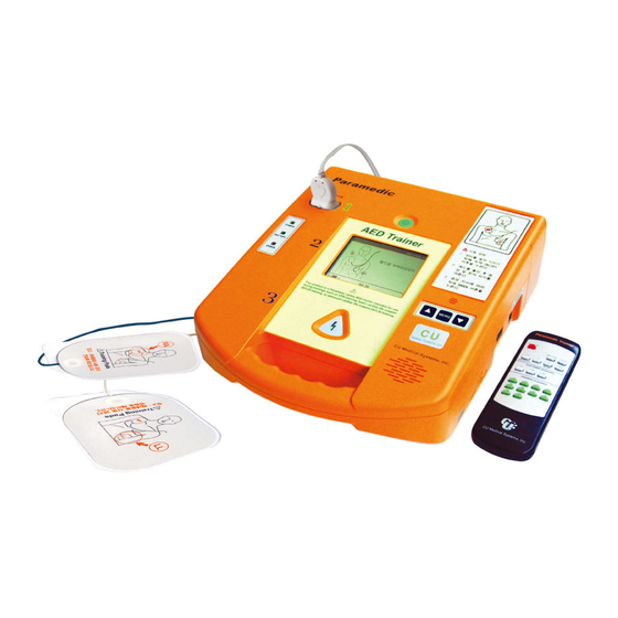
CU-ERT Operator’s Manual_ver 1.10 4.4 Parts and Accessories Infrared remote controller Used to control the training functions of the Paramedic CU-ERT Used to connect the Paramedic CU-ERT to the resuscitation AED Pads mannequin. For simulation only. No signal acquisition and shock deliveries are involved. -
Page 18: Voice And Text Prompts
CHECK PADS instructor operator should press the PAD ON/OFF button on the infrared remote controller. Indicates that the Paramedic CU-ERT is doing an analysis of the ANALYZING ECG patient’s ECG signal. Indicates that the patient has a shockable ECG rhythm such as SHOCK ADVISED VF or VT with rates greater than 150 bpm. -
Page 19: User Interface
CU-ERT Operator’s Manual_ver 1.10 4.7 User Interface The Paramedic CU-ERT has exactly the same user interface as the Paramedic CU-ERT except for the infrared remote controller that is not available on the Paramedic CU-ERT. 4.7.1 LCD Display Splash Screen When the power is turned ON, the following splash screen is displayed on the LCD of the Paramedic CU-ERT. - Page 20 Battery Status Icon Shows the power level of the external battery pack of the Paramedic CU- When the External ERT. It also indicates when the Paramedic CU-ERT is powered by an AC Battery Pack adapter or a Car cigar lighter jack.
- Page 21 BATTERY LEVEL Shows the power level of the external battery pack of the Paramedic CU-ERT. It also INDICATOR; indicates when the Paramedic CU-ERT is powered by an AC adapter or a Car cigar lighter External Battery jack. Pack is Used Battery level >...
-
Page 22: Power Switch And Shock Button
CU-ERT Operator’s Manual_ver 1.10 4.7.2 Power Switch and SHOCK Button Power is turned ON and SHOCK is delivered by activating the Power switch and the SHOCK buttons, respectively. 4.7.3 Menu Buttons The menu is activated and navigated using the Menu Buttons The UP Button scrolls the highlighter up during Menu operation. -
Page 23: Infrared Remote Controller
CU-ERT Operator’s Manual_ver 1.10 4.7.4 Infrared Remote Controller This enables an instructor to control the Paramedic CU-ERT from a distance. Infrared Remote Controller Actual Shape Key Button Markings... - Page 24 CU-ERT Operator’s Manual_ver 1.10 Infrared Remote Controller Functions Function POWER OFF Turns the power of the Paramedic CU-ERT when pressed while the Paramedic CU-ERT is ON. PAD ON/OFF Simulates pads ON and pads OFF conditions. Toggles between the said two conditions when pressed (i.e.
-
Page 25: Light Indicators
Battery – not used in this version of the Paramedic CU-ERT. Error – indicates that an error has occurred. Power Switch Button Backlight – when ON, indicates that the Paramedic CU-ERT is ON. SHOCK Button Switch Backlight – flashes when the SHOCK Button needs to be pressed to simulate the prompt for a SHOCK delivery. -
Page 26: Menu Operation
CU-ERT Operator’s Manual_ver 1.10 4.8 Menu Operation The simulation of the Paramedic CU-ERT menu is activated when the MENU button on the keypad is pressed. MENU button – used to activate the MENU. When the Menu is active, used to select the highlighted option of the Menu. - Page 27 USAGE TIME - Total time that the internal battery pack is used as power supply of the Paramedic CU-ERT. This time is counted since the time when the Paramedic CU-ERT is first used. Only the time when the Paramedic CU-ERT is turned ON will be counted STATUS - Battery charging state: indicates the power level of the internal battery pack.
- Page 28 The list of Rescue Events is given in the following table. Name of Event Event Power ON Indicates the time when the Paramedic CU-ERT is turned ON. Power OFF Indicates the time when the Paramedic CU-ERT is turned OFF Indicates the time when the multifunction rescue pads are...
- Page 29 CU-ERT Operator’s Manual_ver 1.10 To go to USAGE REVIEW press ON – MENU – DOWN – MENU – MENU – MENU The following screens will be displayed: DEVICE INFORMATION 17 Sep 2003 DEVICE HISTORY ATTACH PADS BATTERY HISTORY RETURN 00:00:12...
- Page 30 CU-ERT Operator’s Manual_ver 1.10 4.8.4. ECG Review ECG REVIEW will display the ECG record stored in the internal memory or the SmartMedia Card memory. The ECG data from the latest rescue operation can be scrolled to the right or to the left (earlier or later part of the recording, respectively).
- Page 31 CU-ERT Operator’s Manual_ver 1.10 4.8.5 Voice Review In VOICE REVIEW, the voice recorded during a rescue operation is played back. Voice can be stored only in the SmartMedia Card. Therefore, this will work only if the SmartMedia Card is inserted.
- Page 32 CU-ERT Operator’s Manual_ver 1.10 4.8.6 General Device Setup In the GENERAL DEVICE SETUP, operating parameters such as date, time, voice recording, and printer option can be changed or adjusted by the user. To go to GENERAL DEVICE SETUP, press, ON – MENU – DOWN –DOWN –MENU – MENU – MENU.
- Page 33 CU-ERT Operator’s Manual_ver 1.10 4.8.7 Administration Device Setup In the ADMINISTRATION DEVICE SETUP menu, you can set the “Compression-Breath Ratio” and “ECG Gain”, as follows. To go to ADMINISTRATION DEVICE SETUP, press, ON – MENU – DOWN – DOWN – MENU –...
- Page 34 CU-ERT Operator’s Manual_ver 1.10 4.8.8 Printing Data The ECG data stored in the internal flash memory or the SmartMedia Card can be printed using the optional thermal printer. If the SmartMedia Card is not inserted, the data stored in the internal flash memory is printed.
- Page 35 MENU button. You will then be taken to the next higher level in the system. If you are in the highest sublevel, highlighting the RETURN icon and then pressing the MENU button will take you back to RESCUE mode and the Paramedic CU-ERT will prompt you to ATTACH PADS.
-
Page 36: Device Preparation/Set Up
Check the shipping list to ensure that the unit comes with the complete accessories. 5.2 Power Connection Connect the preferred Power Source to the Paramedic CU-ERT. This is discussed in detail on the Chapter on Power Supply. 5.3 Rescue Setup Connect the plug of the AED pads to the ECG-DEFIB Port of the Paramedic CU-ERT. -
Page 37: Scenarios
This is initiated by pressing the VF key on the Remote Controller. A Ventricular Fibrillation ECG rhythm will be simulated and fed to the Paramedic CU-ERT. The name of the ECG rhythm and the beat rate will be shown on the LCD before the said ECG rhythm is displayed on the LCD screen and while the same ECG rhythm is running. -
Page 38: S1, Training Scenario 1
CU-ERT Operator’s Manual_ver 1.10 6.3.7 S1, Training Scenario 1 This is initiated by pressing the S1 key on the Remote Controller Ventricular Fibrillation with multiple shocks required for conversion. The following will be simulated: Shockable rhythm shock iii. CPR countdown (30:2, 15:2) -
Page 39: S5, Training Scenario 5
CU-ERT Operator’s Manual_ver 1.10 on the LCD screen and while the scenario is running. 6.3.11 S5, Training Scenario 5 This is initiated by pressing the S5 key on the Remote Controller Ventricular Fibrillation with one shock required for conversion followed by refibrillation and then another shock then conversion to non shockable rhythm. -
Page 40: S9, Training Scenario 9
CU-ERT Operator’s Manual_ver 1.10 Rhythm converted to non shockable Normal Sinus Rhythm. Refibrillation to Ventricular Fibrillation after 20 seconds. shock vii. CPR countdown (30:2, 15:2) viii. Rhythm converted to non shockable Normal Sinus Rhythm. The name of the Training Scenario will be shown on the LCD before the said scenario is displayed on the LCD screen and while the scenario is running. -
Page 41: Power Supply
Battery Pack Connecting the Battery Pack The battery pack is connected to the Paramedic CU-ERT through the AC/DC adapter port and the UART Port. The connector of the battery pack is embedded with connectors that match the AC/DC and UART Port connectors. -
Page 42: Ac/Dc Adapter
Mains Plug Power cord Connecting the AC/DC Adapter a. connect the power cord to the power mains outlet and to the AC/DC adapter. b. connect the output of the AC/DC Adapter to the AC/DC Adapter port on the Paramedic CU-ERT. -
Page 43: Data Management
Event data, and Audio Signal Data. When used, the SmartMedia card has to be installed in its port before the Paramedic CU-ERT is turned ON. The device has to be turned OFF before removing the SmartMedia card from its port. -
Page 44: Data Review
Voice Recording option is ON. is displayed when the Voice Recording option is OFF e) Only SmartMedia Cards supplied by the manufacturer are compatible with the Paramedic CU-ERT. Do not use any other kind of flash memory card. -
Page 45: Reviewing Data Using A Smartmedia Card
CU-ERT Operator’s Manual_ver 1.10 8.2.2.3 Reviewing Data Using A SmartMedia Card After installing the SmartMedia Card, turn ON the Paramedic CU-ERT. Activate the menu by pressing the MENU button. Go to REVIEW INCIDENT. The following screen will be displayed REVIEW INCIDENT... -
Page 46: Data Transfer To Personal Computer
SmartMedia Card. See the illustrations on the CU Expert User’s Manual The Paramedic CU-ERT must be set to communicate through its IrDA port by setting the COM PORT to IrDA as outlined in the GENERAL DEVICE SETUP of the section on MENU OPERATION. - Page 47 Connection icon When the Paramedic CU-ERT is communicating, the Communication icon will show moving arrow tips. The Connection icon will show the status of the connection of the Paramedic CU-ERT with the PC during data transmission - signifies that connection has not been made yet. This is also shown at the end of the data transfer process.
-
Page 48: Uart Port
The UART port can be used to transmit data to a PC running the CU Expert ECG Data Management Software. Connect the Paramedic CU-ERT to the PC as specified in the User’s Manual of the CU Expert Data Management Software. Insert the SmartMedia Card if the data to be transferred is in the SmartMedia... - Page 49 The progress of the data transmission will be tracked by a progress bar in the LCD display of the Paramedic CU-ERT. The order of device activation can also be reversed. It is possible to set the Paramedic CU-ERT first to transmit data and then set the CU Expert to receive data.
-
Page 50: Printing Using A Stand-Alone Serial Printer
The optional stand-alone printer is a serial printer configured to receive data using RS232 protocol. The stand-alone printer set that comes with the Paramedic CU-ERT (optional) is composed of the printer, UART cable, AC adapter, AC power cable, ECG printer paper. These are shown in the figure... - Page 51 Paramedic CU-ERT through the UART port. Connect the printer to the Paramedic CU-ERT and at the same time connect the DC output of the AC adapter to the printer power port. In this mode, the AC Adapter is supplying power to the printer.
- Page 52 CU-ERT Operator’s Manual_ver 1.10 Printer Control Buttons and LED Indicators Power Switch – used to turn the power of the printer ON or OFF Mode button – used to change the transmission parameters of the printer Paper Feed Button – used to advance the printing paper. When the button is pressed and then released, the printer paper advances one line.
- Page 53 CU-ERT Operator’s Manual_ver 1.10 Loading Paper into the Printer Open the paper compartment of the printer by pushing the locks inward simultaneously. When the locks are disengaged, pull the paper compartment lid upward. This is shown in the following figure.
- Page 54 AC adapter output to the printer power port. If it is desired to run the printer using power from the Paramedic CU-ERT, do not connect the AC adapter. Do not connect any connector (AED or ECG monitoring pads connector) to the ECG-DEFIB port of the Paramedic CU-ERT.
- Page 55 CU-ERT Operator’s Manual_ver 1.10 The event highlights are displayed. Choose the starting point of the segment to be printed by pressing the UP or DOWN buttons. A highlighter bar will appear and scroll UP or DOWN. Mark the starting Event point by highlighting it with the highlighter bar and pressing the MENU button.
-
Page 56: Maintenance
CU-ERT Operator’s Manual_ver 1.10 9. Maintenance Although there are no user-serviceable parts inside the Paramedic CU-ERT, the user can perform simple maintenance tasks to help prolong the life of the device and to help ensure that the device is in mint condition. - Page 57 CU-ERT Operator’s Manual_ver 1.10 MAINTENANCE CHECKLIST Paramedic CU-ERT Serial Number: __________________ Location/Vehicle ID: ______________ Date Scheduled Frequency Paramedic CU-ERT Clean, no signs of damage, free of excessive wear Supplies Available -2 sets of pads, undamaged, sealed, within expiration date -supplementary supplies...
-
Page 58: Cleaning The Paramedic Cu-Ert
CU-ERT Operator’s Manual_ver 1.10 9.1 Cleaning the Paramedic CU-ERT After each use, clean the Paramedic CU-ERT using a soft, damp cloth moistened with any of the following solvents: Soap and water 70% solution isopropyl alcohol Chlorine bleach and water mixture (30 ml bleach/liter of water) -
Page 59: Troubleshooting Guide
Replace the external batteries if the “LOW BATTERY CODE:0001” prompt is issued when the Paramedic CU-ERT is turned ON with the external battery pack connected or if the empty battery icon is displayed when the Paramedic CU-ERT is ON. Prompts... - Page 60 CU-ERT Operator’s Manual_ver 1.10 APPENDIX A <TECHNICAL SPECIFICATIONS> ECG Monitor (Simulated) • Patient connection: Defibrillation Pads, ECG Electrodes Monitoring Mode: 0.3 to 40 Hz (-3 dB) • Bandwidth: AED mode (EMS): 1 Hz to 30 Hz Auto-scaled (0.3 to 1 mV signals are displayed with 10mm/mV •...
- Page 61 CU-ERT Operator’s Manual_ver 1.10 CU Medical Systems, Inc. Address #534, Dusan VentureDigm,,126-1 Pyeongchon, ■ dongan, Anyang-si, Gyeonggi-do, Republic of Korea ■ TEL : +82-31-478-5725 ■ FAX: +82-31-478-5729 ■ HOMEPAGE : http://www.cu911.com ■ E-mail : admin@cu911.com...
Need help?
Do you have a question about the CU-ERT and is the answer not in the manual?
Questions and answers