Table of Contents
Advertisement
Quick Links
Advertisement
Table of Contents
Troubleshooting

Related Manuals for USA Lab VO Series


Summary of Contents for USA Lab VO Series
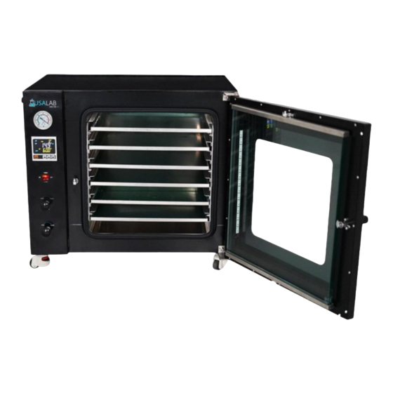
- Page 1 Vacuum Oven Model: VO Series VO-09, VO-19, VO-32...
- Page 2 Index Safety Precautions and Explanations 1. Important Information 1.1 Safety Notices 1.2 Features 1.3 Technical Specifications 2. Diagrams 3. Control Panel Operation 3.1 LCD Display Operation 4. Installation 4.1 Included Items 4.2 Tubing Connections 4.3 Electrical Connection 4.4 Operating Area 4.5 Operating Instructions and Notes 5.
- Page 3 Safety Precautions and Explanations At USA Lab, safety is our number one priority. The following information provides guidelines for safety when using USA Lab equipment. Any piece of machinery can become dangerous to personnel when improperly operated or poorly maintained. ALL employees operating and maintaining USA Lab equipment should be familiar with its operation, thoroughly trained, and Instructed on the best safety practices.
- Page 4 Ensure that all power sources are turned off when the machine is not in use. This encompasses electrical and pneumatic power. • Read the manual for any special operational instructions for each piece of equipment. All USA Lab authored manuals are typically included with each device as well as posted online. •...
-
Page 5: Symbols And Warnings
Symbols and Warnings Below are examples of commonly used symbols and what they mean. Understand them and their potential consequences. -
Page 6: Section 1 | Important Information
Never use a generator to power this equipment. Do not change the length of the power cable. Repairs must be made by USA Lab or by instruction from USA Lab. If there is a problem, do not continue to use the oven. - Page 7 1.2 Features • Standard 110V operation. • Bright white LED lights for full visibility of the trays. • Stainless-steel tubing throughout helps reduce the need to replace old worn tubing. • KF25 vacuum port. • 4-sided heating in the VO-09 & VO-19. 5-sided heating in the VO-32. •...
-
Page 8: Section 2 | Diagrams
1.3 Technical Specifications Technical Specifications VO-09 VO-19 VO-32 Model 110V Single Phase 60Hz Voltage NEMA 5-15p Plug 500 W 1400 W 1500 W Wattage Room + 10°C - 200°C Room + 10°C - 150°C Temperature Range ± 1°C Temperature Accuracy 1 Torr / 1,000 Microns / 1 mmHg(a) Lowest Vacuum Depth KF25 / NW25... - Page 9 Back Connections...
-
Page 10: Section 3 | Control Panel Operation
Section 3 | Control Panel Operation 3.1 LCD Display Operation Buttons: | [SET] Set Menu | [◄/AT] Move Left / Auto Tune | [▼/RES] Decrease / Reset | [▲/◘] Increase / Lock | How to set the heating and timer values: Press SET to enter the programming menu. -
Page 11: Section 4 | Installation
Section 4 | Installation 4.1 Included Items If you are missing any items, contact us. Packing List Vacuum Oven 1 Unit Tubing 11 ft. Barb to KF25 Adapter 1 pc KF25 Gasket and Clamp 1 pc ea 4.2 Tubing Connections 4.4 Electrical Connections Each unit has its own power requirements, please understand their differences. - Page 12 4.6 Operating Instructions and Notes Ensure that you have read and understand section 3.1. You will need to know how to program the controller to operate the equipment. How to use the Over-temperature Protection function of the equipment. The over-temperature protection system is responsible for limiting the heating output of the heater. It does this by using a temperature sensitive mechanical switch.
-
Page 13: Section 5 | Maintenance
Section 5 | Maintenance 5.1 Periodic Maintenance Shut off the power switch AND disconnect the power cord before any maintenance. Use a damp soft cloth to wipe clean. Stubborn stains should be cleaned by neutral detergents. The maintenance of internal electrical and heating parts must be performed by professionals or trained electricians. -
Page 14: Section 6 | Technical Diagrams And Troubleshooting
Section 6 | Technical Diagrams and Troubleshooting 6.1 Circuit Board Diagrams VO-09 & VO-19:... - Page 15 VO-32:...
-
Page 16: Troubleshooting
6.2 Troubleshooting USA Lab VO Series - Troubleshooting Problem Cause Solution A. Plug unit in. A. Unit not plugged in. B. Reset the breaker on rear. B. Breaker has tripped. No Power C. Investigate building power C. No power from outlet. -
Page 17: Section 7 | Warranty Information And Coverages
Within this warranty period USA Lab will replace or repair components that fail during normal daily use. Such repairs or parts will be covered in full by USA Lab and the customer will be responsible for shipping, labor, and custom duties. - Page 18 You will be responsible for the return shipment unless deemed defective by USA Lab. In that case, we will pay for return shipment and replacement shipment costs. • The item(s) must be returned in original packaging and in undamaged condition.
- Page 19 This manual and its contents are subject to change without notice. USA Lab reserves the right of ultimate interpretation of this instruction manual. Additionally, USA Lab is not responsible for damages or injuries caused by improper use; knowingly or unknowingly.
Need help?
Do you have a question about the VO Series and is the answer not in the manual?
Questions and answers