
Related Manuals for Electrolux Professional Compass Pro


Summary of Contents for Electrolux Professional Compass Pro
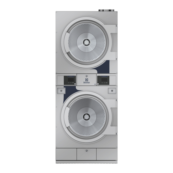
- Page 1 Installation manual Tumble dryer TD6–17S Compass Pro Type N3... 438917586/EN Original instructions 2022.09.12...
-
Page 3: Table Of Contents
Contents Contents 1 Safety Precautions ..........................5 Gas heated tumble dryer ......................7 General safety information......................7 Commercial use only........................7 Copyright ..........................7 Symbols............................8 2 Warranty terms and exclusions......................9 3 Technical data...........................10 Drawing ..........................10 Technical data ......................... 11 Connections ..........................11 4 Setup ...............................12 Unpacking ..........................12 Recycling instruction for packaging ...................13 Siting ............................14... -
Page 5: Safety Precautions
Installation manual 1 Safety Precautions • Servicing shall be carried out only by authorized personnel. • Only authorized spare parts, accessories and consumables shall be used. • The machine is not to be used if industrial chemicals have been used for cleaning. •... - Page 6 Installation manual • Oil-affected items can ignite spontaneously, especially when exposed to heat sources such as in a tumble dryer. The items become warm, causing an oxidation reaction in the oil. Oxidation creates heat. If the heat cannot escape, the items can become hot enough to catch fire.
-
Page 7: Gas Heated Tumble Dryer
The machine/machines covered by this manual is/are made for commercial and industrial use only. 1.4 Copyright This manual is intended solely for consultation by the operator and can only be given to third parties with the permis- sion of Electrolux Professional company. -
Page 8: Symbols
Installation manual 1.5 Symbols Caution Caution, hot surface Caution, high voltage Read the instructions before using the machine... -
Page 9: Warranty Terms And Exclusions
Warranty will be applicable where the customer has used only genuine spare parts and has performed maintenance in accordance with Electrolux Professional user and maintenance documentation made available in paper or elec- tronic format. Electrolux Professional strongly recommends using Electrolux Professional approved cleaning, rinse and descaling agents to obtain optimal results and maintain product efficiency over time. -
Page 10: Technical Data
Installation manual 3 Technical data 3.1 Drawing fig.W00113 Operating panel Door opening, ⌀ 580 mm Electrical connection Gas connection Exhaust connection 1115 1940 1270 1210 1930 1840... -
Page 11: Technical Data
Installation manual 3.2 Technical data Weight, net Drum volume litres 2 x 300 Drum diameter Drum depth Drum speed, medium load Rated capacity, filling factor 1:18 (Max. load) 16.6 Rated capacity, filling factor 1:22 (Recommended load) 13.6 Heating: Electricity 2 x 9 2 x 13.5 2 x 18 Heating: Gas... -
Page 12: Setup
Installation manual 4 Setup 4.1 Unpacking Note! Two persons are recommended for the unpacking. Remove the bolts between the machine and pallet. There are two bolts in the front of the machine and two in the back of the machine. Open the filter door and remove the two bolts in the front of the machine. Remove the lower rear pan- el and remove the bolts in the back of the machine. -
Page 13: Recycling Instruction For Packaging
Installation manual 4.2 Recycling instruction for packaging fig.X02460 Fig. Description Code Type Wrapping film LDPE 4 Plastics Corner protection PS 6 Plastics Cardboard packaging PAP 20 Paper Pallet FOR 50 Wood Screw FE 40 Steel Plastic bag PET 1 Plastics... -
Page 14: Siting
Installation manual 4.3 Siting The figure shows recommended distance to walls and/or other machines. D=C+B 1= Top view 2 = Side view on built in machine Y = For built-in machines it is recommended that the wall section Y is a removable finish piece. If so, E and F can be 0. fig.X00959A 5–500 mm (Min. -
Page 15: Connection To Network
Installation manual 4.4 Connection to network If several machines are to be connected to a network, the knock-outs (A) in the side panels must be removed before installation. A bushing for network cables must be installed from the inside in the right-hand side panel. The bushing must be pushed right through the hole in the left-hand side panel on the side of the machine. -
Page 16: Securing The Machine
Installation manual 4.5.1 Securing the machine To ensure steadiness of the machine it is important to fasten the machine to the foundation. Fasten the four fittings (A) to the foundation using four x M10 set screws (B). If the four fittings are not supplied, order kit No. -
Page 17: Evacuation System
Installation manual 5 Evacuation system 5.1 Air principle The fan creates low pressure in the machine, drawing air into the drum via the heating unit. The heated air passes through the garments and the drum holes. The air then flows out through a lint filter positioned below the drum. Then the air is evacuated through the fan and exhaust system. -
Page 18: Exhaust Duct
Installation manual 5.3 Exhaust duct • Only rigid or flexible metal duct should be used for exhausting. • Plastic ducting is not to be used. • Recommended material for exhaust is galvanized steel. • The duct is not to be assembled with screws or other fastening means that extend into the duct and catch lint. •... -
Page 19: Exhaust Dimensioning
Installation manual Number of machines ⌀ mm Exhaust duct Recommended area 0.32 0.78 1.26 1.26 1.96 1.96 3.12 3.12 3.12 5.02 of fresh air intake Minimum area of 0.12 0.24 0.36 0.48 0.72 0.84 0.96 1.08 fresh air intake The exhaust duct diameter must not be reduced. 5.5 Exhaust dimensioning It is important that the machine has correct air volume compared to each machines power. -
Page 20: Gas Connection
Installation manual 6 Gas connection 6.1 Fasten the label Before installing the machine fasten the label “Read the user instructions” on the inside of the door in a suitable place and at the front panel. The label must have the correct country code, choose the correct label from the gas kit. Read the technical instructions before installing the appli-... -
Page 21: Gas Installation
Installation manual 6.3 Gas installation This gas appliance is build to run on natural gas (group I2H and I2E), commonly identified by GNH. Japan to run on LPG (group I3B/P) 2800 Pa inlet pressure, no regulation. This default gas appliance is built to be installed at not over than 610 m (2001 ft) high altitude otherwise a kit for high altitude must be installed to the machine. -
Page 22: Table Of Pressure And Adjustment
Installation manual 6.4 Table of pressure and adjustment Liquied petro- Gas category Inlet pressure Injector pres- Injector size (⌀ Air reducing Label number May be avail- leum gases (mbar) sure (mbar) plate (mm) able in follow- ing countries Butane mixture 28-30 / No regulation 2.30... -
Page 23: Test Run
Installation manual 6.5 Test run • Loosen the measuring branch screw (2) 1/4 turn; connect a manometer to the measuring branch. • Select a program with heat. • Start the machine. • Check the nozzle pressure, see “Table of pressure and adjustment”. •... -
Page 24: Data Label
INJECTOR:Ø 4.00 NATURAL GAS : G20 (INLET PRESS.: 20-25 MBAR, CAL. VAL. 37780 KJ/M3) For safety reasons use only genuine spare parts. Made in Sweden Electrolux Professional AB 341 80 Ljungby, Sweden WXXXXX 9868XXXXXX Product no.: 09XXX / 99XXXXX Serial no.:... -
Page 25: Electrical Connection
Installation manual 7 Electrical connection 7.1 Electrical installation The electrical installation may only be carried out by qualified personnel. Machines with frequency-controlled motors can be incompatible with certain types of earth leakage circuit break- er. It is important to know that the machines are designed to provide a high level of personal safety, which is why items of external equipment such as earth leakage circuit breakers are not necessary but is recommended. -
Page 26: Electrical Connections
Installation manual Electric heated tumble dryer Demount the cover panel from the supply unit. Connect the earth and other wires as shown. Separate power supplies for top and bottom tumble dryer T = Top tumble dryer L1 L2 L3 L1 L2 L3 B = Bottom tumble dryer When the installation is completed remount the cover panel and check: •... -
Page 27: Functions For I/O-Cards
Installation manual 7.5 Functions for I/O-cards The electrical schematic can be one of the following: 7.5.1 Central payment (2J) To start the machine from a central payment system, the payment system must transmit a start pulse 300–3000 ms (500 ms is recommended) with a minimum pause of 300 ms (500 ms is recommended) between two pulses. The start pulse can be either 230V or 24V. -
Page 28: Central Payment (2J)
Installation manual 7.5.2 Central payment (2J) The central payment or booking system shall transmit an active (high) signal to the machine once permission has been granted to start the machine. The signal must remain active (high) during drying. When the signal gets inactive (low) the machine will abort ongoing program and enter cooling. -
Page 29: External Coin Meter/Central Payment (2K)
Installation manual 7.5.3 External coin meter/Central payment (2K) The signal received from external coin meters must be a pulse between 300–3000 ms (500 ms is recommended) with a minimum pause of 300 ms (500 ms is recommended) between two pulses. fig.7438... -
Page 30: Price Reduction (2K)
Installation manual 7.5.4 Price reduction (2K) By maintaining an activated (high) signal on connection 5 ("Price red"), the price of the program can be reduced. This function has a number of uses, including providing reductions during a specific period of the day. Whilst the signal re- mains active (high), the price of the program is reduced (or the time is increased on time programs), by the percent- age entered in the price programming menu. - Page 31 Installation manual ON position is upwards. fig.W00645...
-
Page 32: At First Power Up
Installation manual 8 At first power up When the installation is complete and the power is connected for the first time you will be forced to make the following settings. When one setting is ready you will automatically enter the next one. Follow the instructions on the display. •... -
Page 33: Function Check
Installation manual 9 Function check May only be carried out by qualified personnel. A function check must be made when the installation is finished and before the machine can be ready to be used. Whenever a repair has been made, a function check must be performed before the machine can be used again. Check the automatic stop of the machine •... - Page 34 Installation manual Check the heat • Let the machine work for five minutes on a program with heat. • Check that the heating is working by opening the door and feel if there is heat in the drum. Ready to use If all tests are OK the machine is now ready to be used.
-
Page 35: Disposal Information
Installation manual 10 Disposal information 10.1 Disposal of appliance at end of life Before disposing of the machine, make sure to carefully check its physical condition, and in particular any parts of the structure that can give or break during scrapping. The machine’s parts must be disposed of in a differentiated way, according to their different characteristics (e.g. - Page 36 Electrolux Professional AB 341 80 Ljungby, Sweden www.electroluxprofessional.com...
Need help?
Do you have a question about the Compass Pro and is the answer not in the manual?
Questions and answers