Table of Contents
Advertisement
Advertisement
Table of Contents

Related Manuals for Fujitsu D2759


Summary of Contents for Fujitsu D2759
- Page 1 System Board D2759 for PRIMERGY TX150 S7 Technical Manual Edition December 2009...
- Page 2 – The contents of this manual may be revised without prior notice. – Fujitsu assumes no liability for damages to third party copyrights or other rights arising from the use of any information in this manual. – No part of this manual may be reproduced in any form without the prior written permission of Fujitsu.
- Page 3 It has not been designed or manufactured for uses which demand an extremely high level of safety and carry a direct and serious risk to life or body if such safety cannot be ensured. Technical Manual D2759 (TX150 S7)
- Page 4 (hereafter, "high safety use"). Customers should not use this product for high safety use unless measures are in place for ensuring the level of safety demanded of such use. Please consult the sales staff of Fujitsu if intending to use this product for high safety use.
- Page 5 Only for the Japanese market: Although described in this manual, some sections do not apply to the Japanese market. These options and routines include: – USB Flash Module (UFM) – CSS (Customer Self Service) – Replacing the lithium battery Technical Manual D2759 (TX150 S7)
- Page 6 Technical Manual D2759 (TX150 S7)
-
Page 7: Table Of Contents
Jumper ......35 Replacing the lithium battery ....37 Technical Manual D2759 (TX150 S7) - Page 8 Contents Technical Manual D2759 (TX150 S7)
-
Page 9: Introduction
DVDs (see Installation DVD of ServerView Suite - ServerView Software Products). You will find further information about the BIOS setup in the “D2759 BIOS Setup Utility for TX150 S7” manual. PRIMERGY manuals are available in PDF format on the PRIMERGY ServerView Suite DVD 2. - Page 10 Introduction Technical Manual D2759 (TX150 S7)
-
Page 11: Important Information
Information on which system expansions are approved for installation can be obtained from our customer service center or your sales outlet. The warranty expires if the device is damaged during the installation or replacement of system expansions. Technical Manual D2759 (TX150 S7) - Page 12 (this information doesn’t apply to the Japanese market). It is essential to observe the instructions in the chapter "Replacing the lithium battery". Technical Manual D2759 (TX150 S7)
- Page 13 Do not touch any connectors or conduction paths on an ESD. Place all the components on a pad which is free of electrostatic charge. For a detailed description of how to handle ESD components, see the relevant European or international standards (EN 61340-5-1, ANSI/ESD S20.20). Technical Manual D2759 (TX150 S7)
-
Page 14: Ce Certificate Of Conformity
The board complies with the requirements of the EC directives 2004/108/EC regarding “Electromagnetic Compatibility” and 2006/95/EC “Low Voltage Directive”. This is indicated by the CE marking (CE = Communauté Européenne). Compliance was tested in a typical PRIMERGY configuration. Technical Manual D2759 (TX150 S7) -
Page 15: Environmental Protection
Environmental protection Environmental protection Environmentally-friendly product design and development This product has been designed in accordance with the Fujitsu standard for "environmentally friendly product design and development". This means that key factors such as durability, selection and labeling of materials, emissions, packaging, ease of dismantling and recycling have been taken into account. - Page 16 Details regarding the return and recycling of devices and consumables within Europe can also be found in the "Returning used devices" manual, via your local Fujitsu branch or from our recycling center in Paderborn: Fujitsu Technology Solutions Recycling Center D-33106 Paderborn Tel.
-
Page 17: Features
– onboard iRMC S2 Server Management Controller with integrated graphics controller and associated service LAN connector – 16 MB SPI Flash (code) and 1 MB SPI Flash (data) for iRMC S2 – 32Mx16-667 DDR2 SRAM for iRMC S2 Technical Manual D2759 (TX150 S7) - Page 18 PCI slots – 5 x PCI-Express slots: – 2x PCIe x8 slots (Gen2) – 2x PCIe x1 slots (Gen1) – 1x PCIe x4 slot (Gen1) – 1 x PCI slot (32 bit / 33 MHz) Technical Manual D2759 (TX150 S7)
- Page 19 – battery in holder Form factor – ATX 305 x 244 mm CSS (Customer Self Service) This system board supports the CSS functionality. You will find a description of CSS functionality in the operating manual of your server. Technical Manual D2759 (TX150 S7)
- Page 20 TPM or the system board is faulty you will not be able to access your data. – If a failure occurs, please inform your service about the TPM activation before it takes any action, and be prepared to provide them with your backup copies of the TPM content. Technical Manual D2759 (TX150 S7)
-
Page 21: Main Memory
The DRAM device technology (1Gbit / 2Gbit) may vary from one channel to the other. – If the amount of memory differs between the two channels, the system board will run in dual-channel asymmetric mode. Technical Manual D2759 (TX150 S7) - Page 22 Quad-Core processors (Xeon 3400 series). Total memory size: up to 32 GB Configuration Max. speed DIMM-3 DIMM-2 DIMM-1 per channel DDR3-1333 empty empty SR/DR DDR3-1066 empty empty DDR3-1333 empty SR/DR SR/DR DDR3-800 empty DDR3-800 SR/DR SR/DR SR/DR Technical Manual D2759 (TX150 S7)
- Page 23 Core processors (e.g. Core i3-540, Pentium G6950, ® Celeron G1101) and by Intel Quad-Core processors (Xeon 3400 series). Total memory size: up to 16 GB Configuration Max. speed DIMM-3 DIMM-2 DIMM-1 per channel DDR3-1333 empty empty SR/DR DDR3-1333 empty SR/DR SR/DR Technical Manual D2759 (TX150 S7)
-
Page 24: Pci Slots
An interrupt signal may thereby be used simultaneously by multiple devices (interrupt sharing). PCI Express devices send their interrupts through messages. The interrupts are defined by the system design. Technical Manual D2759 (TX150 S7) - Page 25 PCI_INTC, PCI_INTD Slot 1 PCI (33 MHz) INTB, INTC, INTD, INTA Assignment of the PCI interrupts If you select Auto in the BIOS setup, the interrupts are assigned automatically and no further settings are required. Technical Manual D2759 (TX150 S7)
-
Page 26: Screen Resolution
16 bit 1280x1024 24 bit 1600x1200 16 bit If you are using an external graphic controller, you will find details of supported screen resolutions in the operating manual or technical manual supplied with the graphic controller. Technical Manual D2759 (TX150 S7) -
Page 27: Temperature / System Monitoring
When voltage exceeds warning level high or falls below warning level low an alert will be generated. Cover monitoring Unauthorized opening of the cover is detected, even when the system is switched off. However, this will only be indicated when the system is switched on again. Technical Manual D2759 (TX150 S7) - Page 28 BIOS Setup, iRMC S2’s Web interface or via the ServerView Operations Manager. PRIMERGY Local Diagnostic LEDs Optical signaling through the LEDs on the system board identifies defective modules and components (CSS functionality) as well as gaining information on the PDA (Prefailure Detection and Analysis). Technical Manual D2759 (TX150 S7)
-
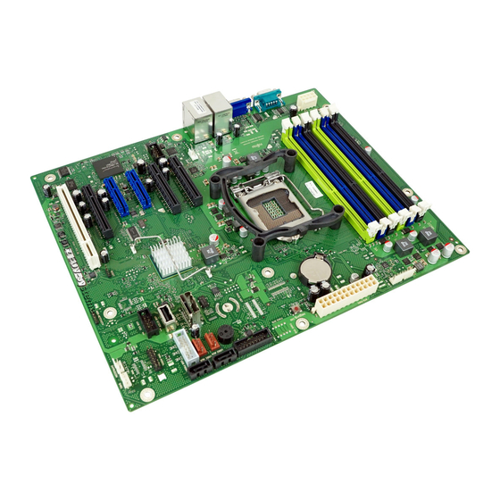
Page 29: Connectors And Indicators
USB1 AUX Slot 3 jumper Front stick PCIe x4 Reset Slot 2 USB SSD PCI 32 Bit / 33 MHz Intrusion HDD Activity Slot 1 SMB1 Figure 5: Internal connectors of the system board D2759 Technical Manual D2759 (TX150 S7) - Page 30 USB stick connector USB SSD Connector for USB Flash Module (UFM) HDD Activity Connector for HDD activity LED Reset Connector for RESET switch Serial 2 Connector for second serial interface FAN1 SYS Connector for system fan 1 Technical Manual D2759 (TX150 S7)
- Page 31 LED´s of the memory modules the air duct (including system fan) has to be removed. If the server has been powered off (power-plugs must be disconnected) it is possible to indicate the faulty component by pressing the CSS indicate button. Technical Manual D2759 (TX150 S7)
- Page 32 F - PCI card PCI card okay orange on PCI card failure G - AUX power yellow on all aux voltages okay H - iRMC green flashing iRMC S2 is okay Technical Manual D2759 (TX150 S7)
-
Page 33: Connector Panel
(blue); (description see preceding section) Depending on the settings in the BIOS, the system LAN connector may also be used as a service LAN connector. You will find further information in the "D2759 BIOS Setup Utility for PRIMERGY TX150 S7" manual. - Page 34 Remains dark in the event of a LAN transfer rate of 10 Mbit/s. Steady green signal when a LAN connection exists. link/transfer Remains dark when no LAN connection exists. (system LAN) Flashes green when LAN transfer takes place. Technical Manual D2759 (TX150 S7)
-
Page 35: Jumper
PCI 32 Bit / 33 MHz Intrusion HDD Activity Slot 1 SMB1 default PWD SKIP RCVR Figure 9: Jumper Setting Description Default Password skip disabled and recovery BIOS disabled. RCVR Recovery BIOS enabled. PWD SKIP Password skip enabled. Technical Manual D2759 (TX150 S7) - Page 36 Connectors and indicators Features Technical Manual D2759 (TX150 S7)
-
Page 37: Replacing The Lithium Battery
Ê Press the locking spring into direction of the arrow (1), so that the lithium battery jumps out of its socket. Ê Remove the battery (2). Ê Insert a new lithium battery of the same type into the socket (3) and (4). Technical Manual D2759 (TX150 S7) - Page 38 Replacing the lithium battery Technical Manual D2759 (TX150 S7)
Need help?
Do you have a question about the D2759 and is the answer not in the manual?
Questions and answers