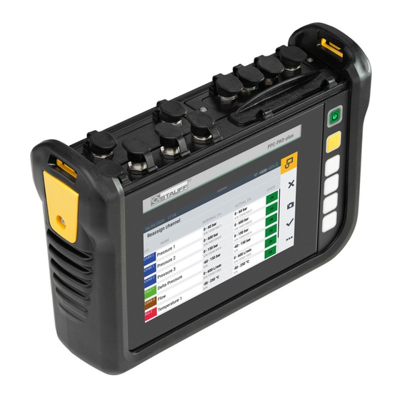
STAUFF PPC-PAD-plus Operating Manual
Hide thumbs
Also See for PPC-PAD-plus:
- Quick reference manual (16 pages) ,
- Operating manual (140 pages)
Table of Contents
Advertisement
Quick Links
Advertisement
Table of Contents

Related Manuals for STAUFF PPC-PAD-plus


Summary of Contents for STAUFF PPC-PAD-plus
- Page 1 Operating Manual PPC-PAD-plus...
- Page 2 First edition The information contained in this document may be neither distributed nor copied in whole or in part without express consent from STAUFF. All brand names and trademarks mentioned in this document, including those protected by third- parties, are subject, unconditionally, to the provisions of the applicable trademark legislation and property rights of the registered legitimate owner.
-
Page 3: Table Of Contents
Design and Function ..................18 Overview ...................... 19 Functions and Features .................. 20 Connections ....................21 3.3.1 STAUFF CAN / External CAN ............... 22 3.3.2 D-IN/D-OUT F1/F2 ..................24 Connection Ports - Input Modules ..............25 Input Modules ....................26 4.4.1... - Page 4 Measurement Views ..................52 6.3.1 List 6 View ....................53 6.3.2 List 12 View ....................54 6.3.3 Manometer View ..................55 6.3.4 Trend Graph View ..................56 6.3.5 Analyzing the Measurements ..............59 6.3.6 Edit Channels .................... 62 Measurement Status ..................65 www.stauff.com...
- Page 5 CAN X ....................... 92 6.10.2 CAN Y ....................... 92 6.10.3 D-IN/D-OUT F1/F2 ..................94 6.10.4 Input Modules A and B ................98 6.10.5 Calculating Channels ................100 6.11 Connections ....................102 6.11.1 Wireless & Networks................103 6.11.2 Remote Desktop ..................104 www.stauff.com...
- Page 6 Repairing ....................124 Disposal ......................125 Technical Data ....................126 11.1 Device Model ....................126 11.2 Mechanical Data ..................126 11.3 Touchscreen Data ..................126 11.3.1 Power Supply (External) ................127 11.3.2 Power Supply (Internal) ................127 11.3.3 Memory ....................127 www.stauff.com...
- Page 7 USB Host ....................129 11.5.3 LAN ......................129 11.5.4 Wifi (WLAN) .................... 129 11.6 Analog Input Modules .................. 130 11.6.1 Connections, STAUFF Sensors ..............130 11.6.2 Connection, External Sensor..............130 11.7 Can Input Module ..................131 Appendix ......................132 12.1 Accessories ....................132 12.2...
- Page 8 About this Operating Manual This operating manual is a component part of STAUFF PPC-PAD-plus and contains important information on the intended use, safety, operation and maintenance of the device described. Subject to change without prior notice. Before each step, read the corresponding information carefully and adhere to the sequence of steps described.
-
Page 9: Product Description
Alternatively, the main functions can be selected via the six hardware keys. The USB and LAN connections or wifi (WLAN) interface can be used to connect STAUFF PPC- PAD-plus with a PC or local network to analyze the measured values. -
Page 10: Improper Use
The device does not comply with Directive 94/9/EC and, therefore, must not be used in potentially explosive atmospheres. Conformity The device fulfills the requirements of the following standards and legal regulations: www.stauff.com... -
Page 11: Equipment Supplied
Further information is available in Chapter & "Certificates" on Page 132. Equipment Supplied Check the parts included in the supply package prior to starting up the device. If any- thing is missing, please contact your sales outlet. PPC-PAD-plus Power adapter (110/240 V – 24 V / 3.750 mA) Country adapters (EN, US, UK, AUS) USB cable (2.0) -
Page 12: Notation
Risk of property damage. Probability of occurrence: possible. 2.1.2 Warnings The warnings are structured as follows in this operating manual: DANGER Type and source of the risk Consequences of failure to observe the warning Measures to avoid the risk www.stauff.com... -
Page 13: Basic Warnings
Consequences of failure to observe the warning Measures to avoid the risk Basic Warnings DANGER Risk of explosion through operating electronic devices in potentially explosive atmo- spheres. Risk of fatal or severe personal injury. Observe the provisions and precautionary measures applicable for potentially explosive atmospheres. www.stauff.com... - Page 14 Do not use the device in connection with defective cables and plugs. Cables and plugs must always be shielded. Follow all special rules and switch the device off when its use is forbidden or you are in doubt as to whether interference or risks could result from its use. www.stauff.com...
-
Page 15: Safety-Related Warnings
Never immerse the device in water or other liquids. Never attempt to repair the device yourself. The device may only be repaired by STAUFF. Never clean the device with substances containing solvents. The device may only be cleaned in the way described in Section "Cleaning". -
Page 16: Design And Function
Design and Function Design and Function This chapter contains information on the design of the device and the functions pro- vided. The connection ports, pin assignments and interfaces available on the device are de- scribed. www.stauff.com... - Page 17 Design and Function INFORMATION Information on the input modules is provided in Chapter ""Input Modules" on Page 26. www.stauff.com...
-
Page 18: Overview
Design and Function Overview www.stauff.com... - Page 19 (power connection, CAN X, CAN Y, D-IN/D-OUT F1/F2) Input module A (option) Input module B (option) Communication ports (2 × USB Host, 1 × USB Device, LAN) and SIM card slot On/Off key Context-sensitive function keys Screen (touchscreen) Shock protection www.stauff.com...
-
Page 20: Functions And Features
For recording, saving and analyzing measured data Various types of measurement and their representation Module slots to extend system with input modules LAN connection port Wireless interfaces (option): Bluetooth LE, WLAN, LTE Fold-out stand VESA standard for wall installation www.stauff.com... -
Page 21: Connections
To connect a network cable More information on the sensor connection ports is available in the following chapters. INFORMATION Do not connect the device via the LAN and USB ports simultaneously when transmit- ting data to PPC-Analyze. This will prevent any disturbance. www.stauff.com... -
Page 22: Stauff Can / External Can
STAUFF CAN / External CAN You can use the CAN X and CAN Y ports to connect the device via CAN BUS lines and additional Y-junctions to up to 24 STAUFF sensors (max. 24 channels ) with automatic sensor detection (STAUFF CAN). - Page 23 Page 89. INFORMATION It is not possible to mix operation on one CAN bus using sensors with automatic sen- sor detection (STAUFF CAN) and external sensors without automatic sensor detection (External CAN). IMPORTANT The internal terminating resistor of the CAN-Y is fixed. Do not switch the device to the bus via a stub.
- Page 24 Refer to the following overview for the PIN assignment: Fig. 5 Connection port, D-IN/D-OUT F1/F2 D-IN/D-OUT F1/F2 Digital-In+ Frequency signal 1 Digital-In GND Frequency signal 1 GND Digital-Out+ Frequency signal 2 Digital-Out GND Frequency signal 2 GND +Ub (+24 V +Ub (+24 V www.stauff.com...
-
Page 25: Connection Ports - Input Modules
Input module, SLOT A First slot for an input module Input module, SLOT B Second slot for an input module Further information on the input modules available, the corresponding connections and PIN assignment is available in Chapter "Input Modules" on Page 26. www.stauff.com... -
Page 26: Input Modules
Input Modules Input Modules This chapter provides information on the input modules available. INFORMATION The input modules can be obtained separately. To do this, contact your sales outlet. www.stauff.com... -
Page 27: Inserting The Input Module
2 Remove the dummy cover from the slot and keep it in a safe place. 3 Insert the input module (2) in the slot. 4 Tighten the two screws (1) hand-tight. Ä The input module is installed and ready to operate. Fig. 7 Insert the input module www.stauff.com... -
Page 28: Analog Input Module
Analog Input Module The analog input module is equipped with three analog connection ports, IN1-3, for sensors with automatic sensor detection (STAUFF analog) and an analog connection, IN4/5, for up to two external sensors without automatic sensor detection (e.g. standard industrial sensors). - Page 29 Refer to Chapter & "Input Modules A and B" on Page 96. 4.4.3 Can Input Module The Can Input Module is equipped with two passive CAN bus connections for external sensors without automatic sensor detection (external CAN). www.stauff.com...
- Page 30 The figure indicates the connection ports on the analog input module: Fig. 10 Can Input Module Pos. Designation Description CAN bus (CAN1xx) To connect sensors without automatic sensor detection CAN bus (CAN2xx) To connect sensors without automatic sensor detection Refer to the following overview for the PIN assignment: www.stauff.com...
- Page 31 CAN Low After connecting the sensors without sensor detection, complete the necessary set- tings for the electrical connection and expected signal according to the properties of the sensors connected. Refer to Chapter & "Input Modules A and B" on Page 96. www.stauff.com...
-
Page 32: Starting Up
If the charge status of the integrated battery drops below a specific value, the measurement in progress is stopped. The measured values and user param- eters are automatically saved. The device switches off automatically. Switching the Device On and Off Switching the Device On www.stauff.com... -
Page 33: Connecting The Sensors
Ä The SHUT DOWN button appears in the display. 2 Press the SHUT DOWN button. Ä The device is switched off. Connecting the Sensors Before the device can be used to take measurements, the sensors required for the measurement must be connected. www.stauff.com... -
Page 34: Using The Stand
Using the Stand You can setup the device on a flat surface and use the fold-out stand to improve vis- ibility. The stand can be folded out to a maximum angle of 40°. www.stauff.com... -
Page 35: Mounting The Device
2 Set the device down on a level surface. Mounting the Device If necessary, you can mount the device on a wall after assembling the VESA holder (100 mm × 100 mm) on the rear panel of the device. www.stauff.com... - Page 36 Starting Up Fig. 14 Assembling the holder Mount the device in the following sequence: 1 Assemble the VESA holder at the installation location. Observe the information in the manual supplied with the VESA holder. www.stauff.com...
-
Page 37: Operation
(M4 metric) are included in the supply package. Operation This chapter contains information on the basic operation of the device. Basic Factors The device is immediately ready for use after being started up. The sensors connected are normally displayed in the list view. www.stauff.com... -
Page 38: Operating The Device
The device is mainly operated by using the buttons provided on the touchscreen. You can use your fingers or an appropriate input tool. Alternatively, the main functions can be selected using the context-sensitive function keys. The following overview illustrates the possible finger movements and their functions: Finger movements Function www.stauff.com... - Page 39 The four context-sensitive function keys are used to initiate the functions according to the corresponding button in the menu area of the touchscreen. Function www.stauff.com...
- Page 40 A screen keyboard appears with which to enter digits and characters. Further information on the buttons available is provided in Chapter & "Screen De- sign" on Page 41. www.stauff.com...
-
Page 41: Screen Design
Operation Screen Design This chapter contains information on the basic layout of the screen and the positions of the screen elements. www.stauff.com... -
Page 42: Status Bar
To initiate the main functions Button, Options To unhide/hide the options 6.2.1 Status Bar The status bar displays various symbols to indicate certain system states and general information such as date and time. The table below indicates the possible symbols: www.stauff.com... - Page 43 Battery charge status as an icon Active connection to PPC-Analyze or online measurement in progress 6.2.2 Quick Start Menu You can open the Quick Start menu via the status bar. The Quick Start menu displays information and provides the option of defining settings. www.stauff.com...
- Page 44 1 Swipe from the top screen edge downwards. Ä The Quick Start menu opens. 2 Swipe upwards over the QuickStart menu. Ä The Quick Start menu closes. Further information on setting WLAN connections is available in Chapter & "Connec- tions" on Page 100. www.stauff.com...
-
Page 45: Screen Keyboards
Open the Settings menu by tapping on the gearwheel symbol. 6.2.3 Screen Keyboards A screen keyboard appears in the display to enter texts and digits. The screen keyboard automatically appears when you select the corresponding input field. The following keyboard is available to enter texts and digits: www.stauff.com... - Page 46 Screen keyboard, characters and digits INFORMATION The keyboard layout varies according to various languages and can be changed. The following keyboard layouts are available: QWERTZ, QWERTY, AZERTY. Refer to Chapter & "Device" on Page 105. The following keyboard is available to complete basic arithmetical operations: www.stauff.com...
-
Page 47: Menu Area
The menu area displays up to four buttons with main functions, depending on the cur- rent view. These functions can also be operated using the context-sensitive function keys on the device. Not all the functions are always available. The table below indicates the possible buttons: Symbol Function www.stauff.com... - Page 48 Switch between measurement views Switch to the last menu option Create a screenshot of the current view Switch to the main menu Unhide/Hide the options Display information on the current measurement Symbol Function Add an entry Edit a setting www.stauff.com...
-
Page 49: Options
Zoom out from current view 6.2.5 Options If the options are available as buttons, they can be unhidden and hidden by means of button. The functions available relate to the current view. The table below indicates the possible buttons in the measurement views: www.stauff.com... -
Page 50: Resetting Values
With regard to resetting certain values, there are further optional functions available via the Reset button: 1 Tap on the button. Ä The options are displayed. 2 Tap on the Reset button. Ä The functions available are displayed: Designation Description Delta to zero Reset delta to zero www.stauff.com... -
Page 51: Measurement Views
Before completing a measurement, you can edit the channels and adjust them as necessary. Further information on adjusting channels is available in Chapter & "Edit Channels" on Page 61. Changing the Measurement View You can switch between the individual measurement views: 1 Tap on the button. Ä The next measurement view appears. www.stauff.com... -
Page 52: List 6 View
It is possible to switch between the individual measurement views while a measure- ment is in progress. 6.3.1 List 6 View The List 6 view provides a detailed view of the channels. If more than six channels are active, you can scroll through the list. www.stauff.com... -
Page 53: List 12 View
The List 12 view displays an overview of the active channels and their current mea- sured values. This view enables you to follow twelve channels in one view. If more than twelve channels are active, you can scroll through the list. www.stauff.com... -
Page 54: Manometer View
6.3.3 Manometer View The manometer view displays the current, minimum and maximum measured value as well as the measuring range full scale value for each channel. If more than four channels are active, you can scroll through the list. www.stauff.com... -
Page 55: Trend Graph View
The yellow range in the manometer indicates the defined warning value, the red range the defined alarm value. 6.3.4 Trend Graph View The trend graph view can display up to eight channels in the form of trend curves on a graph. The trend graph view displays the current measured values. www.stauff.com... - Page 56 A maximum of eight channels can be displayed simultaneously as trend lines in the trend graph view. Scroll through the list to the right or left to display further channels: 1 Tap on any channel. 2 Swipe to the right or left. www.stauff.com...
- Page 57 You can use your fingers on the trend graph view to adjust the size of the graph: 1 Tap with two fingers on the screen and drag the fingers apart. Ä The graph is enlarged. 2 Tap with two fingers on the screen and drag the fingers towards each other. www.stauff.com...
-
Page 58: Analyzing The Measurements
Ä The graph is reduced in size again. 3 Tap twice with a finger on the screen. Ä The graph is scaled to 100%. 6.3.5 Analyzing the Measurements You can analyze measurements which have been saved by using the curve tools. www.stauff.com... - Page 59 In order to analyze measurements which have been saved, various functions are avail- able using the options provided after pressing the Curve tools button: 1 Open one of the measurements previously saved. Further information is avail- able in Chapter & "File Manager" on Page 87. www.stauff.com...
- Page 60 Adjust the scaling of the axes 4 Tap on the appropriate button. Ä The function selected is performed. Analyzing the Measured Value Graphs After selecting the Jump to MIN, Jump to MAX or Cursor ON/OFF function, a blue menu bar appears containing additional buttons. www.stauff.com...
-
Page 61: Edit Channels
You can select various channels and use the cursor to complete evaluations of the graph curves. 6.3.6 Edit Channels You can use the Edit channels button to edit the channels in the measurement views. The functions can be used to hide or activate/deactivate individual channels. 1 Tap on the button. www.stauff.com... - Page 62 2 Tap on the Edit channels button. Ä The window in which to edit the channels opens. Fig. 29 Edit channels Pos. Description Edit the colors of the channels Enter/Edit the names of the channels Activate/Deactivate channels (measured value are not saved) www.stauff.com...
- Page 63 4 Define the parameters as required. 5 Tap on the button to activate the setting. Ä You have now edited the channel successfully. *This option was not available at the time of the manual going to print. www.stauff.com...
- Page 64 You can define the number of decimal places, the unit and the minimum and maxi- mum alarm and warning values for each channel. If a channel reaches a defined alarm or warning value, the current measured value is displayed in color in the bar graphs. www.stauff.com...
-
Page 65: Measurement Status
The current runtime of the measurement is displayed underneath the Start/Stop but- ton. 2 Tap on the Start/Stop button. Ä The measurement is stopped. Measuring Methods The device is provided with the following measuring methods: www.stauff.com... -
Page 66: Start/Stop
The button displays the name of the measuring method selected (e.g. Start/Stop). Fig. 31 Measuring methods 6.5.1 Start/Stop The Start/Stop measuring method starts the recording of the measured values after tapping on the Start/Stop button. Recording is stopped by tapping on the Start/Stop button again. www.stauff.com... -
Page 67: Data Logger
The Data logger measuring method starts recording of the measured values by tap- ping on the Start/Stop button. Recording is stopped after a defined storage time has elapsed or by tapping on the Start/Stop button. After selecting the Data logger measuring method, the device displays predefined pa- www.stauff.com... - Page 68 If this option is activated, the defined memory area is continuously overwritten by current measured data Recording MIN/MAX If this option is activated, the Min and Max measured values are also recorded in addition to the current measured value www.stauff.com...
- Page 69 Operation Fig. 32 Data logger, settings The file size expected and maximum storage time for the measurement are calculated and displayed according to the applicable, defined parameters. www.stauff.com...
-
Page 70: Point Measurement
After selecting the Point measurement measuring method, the device displays a pre- defined trigger to start the measurement. 1 Tap on the button. Ä The configuration window to select the trigger opens. 2 Select a trigger source according to your application. www.stauff.com... - Page 71 Measurement is started by tapping on the Start/Stop button. The device waits for the defined trigger to be triggered. Recording of a measured point starts when the defined trigger is triggered. Measurement is stopped by tapping on the Start/Stop button. www.stauff.com...
-
Page 72: Trigger
If this option is activated, the defined memory area is continuously overwritten by current measured data The file size expected and maximum storage time for the measurement are calculated and displayed according to the applicable parameters selected. The table below contains information on the triggers available: Designation Description www.stauff.com... - Page 73 Measurement is started by tapping on the Start/Stop button. The device waits for the defined trigger to be triggered. Recording of a measured value starts when the defined trigger is triggered. Measurement is stopped when the defined storage time has expired or the Start/Stop button is tapped. www.stauff.com...
-
Page 74: Trigger Logic
The Trigger logic measuring method starts recording of the measured values after one or two defined triggers are triggered. Recording is stopped after one or two defined triggers are triggered. INFORMATION Please note that you must define the start/stop conditions in order to be able to use this measuring method. www.stauff.com... - Page 75 1 Tap on the button. Ä The configuration window opens in which to define the parameters. 2 Select a trigger and define the parameters trigger according to your application. The table below contains information on the triggers available: Designation Description www.stauff.com...
- Page 76 Please note that the D-IN connection must be activated for the external trigger. Refer to Chapter & "D-IN/D-OUT F1/F2" on Page 93. The measurement is started after one or two defined triggers are triggered. The measurement is stopped after one or two defined triggers are triggered or tapping on the Start/Stop button. www.stauff.com...
-
Page 77: Fast Measurement
Trigger logic, settings 6.5.6 Fast Measurement The Fast measurement measuring method (FAST MODE) enables the recording of measured values from upto four fast channels. In the case of these fast channels, the measurement is performed at a storage interval of 100 µs. www.stauff.com... - Page 78 The table below contains information on the triggers available: Designation Description Keystroke Measurement is started by tapping on the corresponding but- Level Measurement is started on exceeding or dropping below a limit value www.stauff.com...
- Page 79 Please note that the D-IN connection must be activated for the external trigger. Refer to Chapter & "D-IN/D-OUT F1/F2" on Page 93. Measurement is started when the trigger is triggered and stopped when the defined storage time has expired or the Start/Stop button is tapped. www.stauff.com...
-
Page 80: Completing A Measurement
Operation Fig. 37 Fast measurement, settings Completing a Measurement The description below explains how to complete a measurement according to an ex- ample: www.stauff.com... -
Page 81: Project Management
An SPC serves for: project-related compilation of measured data, templates and media data exchanging with colleagues or other organizations compressing the measured data which reduces the memory space required on a USB stick. It has no effect on the internal device memory. www.stauff.com... -
Page 82: Spc (Service Project Container)
Media: PDF files, screenshots, photos, videos* etc. These settings can be used as templates for new measuring tasks. An SPC can contain and manage several different measuring tasks. *This option was not available at the time of the manual going to print. www.stauff.com... -
Page 83: Creating An Spc (Service Project Container)
Chapter & "Connecting the Sensors" on Page 33. 2 Set the measurement view required. Further information is available in Chapter "Edit Channels" on Page 61. 3 Open the options and tap on the Save Template as button. www.stauff.com... - Page 84 4 Enter a name for the template in the Name field. 5 If necessary, enter an appropriate comment regarding the measurement or the project in the Comment field. 6 Select a storage location in the Storage location field. 7 Tap on the SPC - Service Project Contai... field. www.stauff.com...
- Page 85 If necessary, select an existing SPC or tap on the button to add a new SPC. 8 Enter a name for the new SPC (Service Project Container) in the Name field. 9 Select a storage location for the Service Project Container (SPC) in the Storage field. www.stauff.com...
-
Page 86: Menu
Ä The Save template window opens again. 11 Tap on the button to save the template. Ä The new template and new Service Project Container (SPC) have now been created. Menu The Menu can be opened by tapping the button. www.stauff.com... -
Page 87: File Manager
Refer to Chapter & "Settings" on Page 104 Use the button to return to the measurement view. File Manager The File manager menu is used to administrate the Service Project Container (SPC), templates, measurements and related files stored on the various storage media. www.stauff.com... -
Page 88: Managing Files
An overview of the occupied and total number of storage locations 6.9.1 Managing Files The management of files is independent of the storage medium selected. After selecting a storage medium (e.g. Device Memory), the following functions are available via the options: Designation Description www.stauff.com... -
Page 89: Sensors
The Menu is comprised of a series of tiles which provide a preview of the settings contained in them. Each tile can also be used as a button to open the corresponding submenu. If no input modules are implemented, the tiles (A, B) are grayed out. www.stauff.com... -
Page 90: Can X
Operation Fig. 45 Sensors Pos. Designation Description CAN X Information on the CAN X connection port CAN Y Information on the CAN Y connection port, setting and parameterization D-IN/D-OUT Information on the connection port, setting and param- F1/F2 eterization www.stauff.com... - Page 91 B IM standard Setup and parameterization of the connection ports on input module A 6.10.1 CAN X The CAN X tile displays the following information: Designation Description CAN type Current operating mode Baud rate Current Baud rate www.stauff.com...
- Page 92 Operation Up to 24 STAUFF sensors (max. 24 channels) can be connected to the CAN X port. Other setting adjustments are also possible. 6.10.2 CAN Y The CAN Y tile displays the following information: Designation Description CAN type Current operating mode...
- Page 93 DIGITAL-IN and DIGITAL-OUT Frequency 1/ Frequency 2 Two-channel frequency for volume flow Two-channel frequency Frequency connection with rotation direction detection D-IN State (0/1) Operating mode D-IN D-OUT State (0/1) Operating mode D-OUT Setup the selected operating mode according to your application. www.stauff.com...
- Page 94 Conditions A and B Conditions A or B The following triggers are available for the conditions: Condition A Condition B Level Level Window Window Time External External Channel warning value Channel alarm value The table below contains information on the triggers available: www.stauff.com...
- Page 95 The following measuring methods are available for the Frequency 1 connection : Designation Description Frequency Measurement of the frequency Rotational speed Measurement of the rotational speed Flow rate Measurement of the flow rate Define the settings according to your application. www.stauff.com...
-
Page 96: Input Modules A And B
The Input module A and Input module B tiles display information on the connections and sensors connected according to the input module implemented. Further options are available for setup and configuration according to the input module and connections available. For further information, refer to the & Technical Data related to the sensors. www.stauff.com... - Page 97 There are two methods with which to connect sensors without sensor detection to the device. Method 1: Direct connection to the analog IN4/5 connection on the analog input mod- ule in accordance with the figure: Fig. 49 PIN assignment of sensors without sensor detection Designation www.stauff.com...
-
Page 98: Calculating Channels
6.10.5 Calculating Channels The Calculating channels tile displays the following information: Designation Description The calculation type for channel 1 The calculation type for channel 2 www.stauff.com... - Page 99 In addition to the calculation types available, freely editable equations can be created with up to three variable channels. The formula library contains standard formulas and new formulas can be saved in the user formula library. Define the calculation types according to your application. www.stauff.com...
-
Page 100: Connections
The Connections menu contains settings related to the individual connection methods of the device. The menu is comprised of a series of tiles which provide a preview of the settings contained in them. Each tile can also be used as a button to open the corresponding submenu. www.stauff.com... - Page 101 Operation Fig. 51 Connections Pos. Designation Description Wireless & Networks Settings for wifi, LAN, Bluetooth, mobile communi- cation, proxy server www.stauff.com...
-
Page 102: Wireless & Networks
Status of the mobile communication The submenu enables you to define settings for wifi and LAN connections and to con- nect or disconnect the respective connection: Fig. 52 Wireless & Networks 6.11.2 Remote Desktop The Remote desktop tile displays the following information: Designation Description www.stauff.com... - Page 103 The maximum length of the password is 8 characters. The VNC service is available to use the remote desktop connection. To use the remote desktop connection, you must authenticate yourself with the user name and password. www.stauff.com...
-
Page 104: Settings
The Menu is comprised of a series of tiles which provide a preview of the settings or corresponding information contained in them. Each tile can also be used as a button to open the corresponding submenu. Fig. 54 Settings Pos. Designation Description Device Settings on the device www.stauff.com... -
Page 105: Device
Time until the display is dimmed Tones Volume of the device for various notifications Position determination Switch the GPS on and off, select the system for GPS Language Languages Time/Date Time and date Keyboard QWERTZ / QWERTY / AZERTY www.stauff.com... -
Page 106: User
Designation Description Name Name of the user Company Name of the company Department Name of the department Phone number Landline phone number Mobile phone number Mobile phone number The menu contains further information and options to edit the information. www.stauff.com... - Page 107 Operation INFORMATION Information is voluntary. All the functions on the device can be used even without this information. To improve assignment, the name entered is added when a measurement is saved. www.stauff.com...
-
Page 108: System
Read out and update the firmware version Information on completing a data backup is available in Chapter & "Creating a Backup" on Page 111. Information on resetting the device is available in Chapter & "Resetting the Device to its Default Settings" on Page 117. www.stauff.com... -
Page 109: Service
Operation Fig. 57 System 6.12.4 Service The Service tile displays links to the manufacturer's website. 6.12.5 Information The Information tile displays the following information: Name of the device www.stauff.com... - Page 110 Name, serial number, order code, hardware version, firmware version, next calibration Memory Internal memory, USB1, USB2, network drive, cloud Battery Capacity, voltage, current, battery temperature, remaining charge time, remaining operating time, number of charge cycles User manual Operating manual www.stauff.com...
-
Page 111: Creating A Backup
1 Connect a storage medium (e.g. USB stick) to save the data. 2 Tap on the button. 3 Navigate to the Settings > System > Save & Reset menu option. 4 Tap on the Create backup button. www.stauff.com... - Page 112 Operation 5 Select the storage medium (e.g. USB1) in the Storage location area. www.stauff.com...
-
Page 113: Restoring A Backup
Please note that when restoring data from a backup, the firmware saved on the backup is also restored. 1 Connect the storage medium (e.g. USB stick) which contains the data backup. 2 Tap on the button. 3 Navigate to the Settings > System > Save & Reset menu option. 4 Tap on the Restore backup button. www.stauff.com... - Page 114 Operation 5 Select the storage medium (e.g. USB1) in the Storage location area. 6 Select the data backup required from the Backup file area. www.stauff.com...
-
Page 115: Troubleshooting
Always ensure that the latest version of the firmware is installed on the device. Further information on updating the firmware is available in Chapter & "Updating the Firm- ware" on Page 118. If you find no solution to your problem in this user manual, contact the relevant sales www.stauff.com... -
Page 116: Restarting The Device
Only initiate a restart of the device when it is absolutely necessary. 1 Press the On/Off switch and yellow function key simultaneously for approx. 3 seconds. Ä The device is switched off. 2 Press the On/Off key. Ä The device starts up again. www.stauff.com... -
Page 117: Resetting The Device To Its Default Settings
& "Creating a Backup" on Page 111. IMPORTANT All the settings and parameters are returned to their default settings following a reset. 1 Tap on the button. 2 Navigate to the Settings > System > Save & Reset menu option. 3 Tap on the Reset device to default settings button. www.stauff.com... -
Page 118: Updating The Firmware
Please note that the files for the firmware version on the USB stick must be in the main folder. 1 Tap on the button. 2 Navigate to the Settings > System > Software update menu option. 3 Tap on the Check for update button. www.stauff.com... - Page 119 Troubleshooting Ä The device searches for a firmware version update. www.stauff.com...
- Page 120 6 Wait until the process has finished. Ä The device restarts several times during the process. Ä When the process has been completed, the corresponding message appears in the display. Ä The latest version of the firmware is now installed on the device. www.stauff.com...
-
Page 121: Packaging And Transporting
Contact your sales outlet prior to dispatch. Only dispatch the device in packaging which has been appropriately identified on the outside. Cleaning and Maintenance This chapter contains information on cleaning, servicing and repairing the device. www.stauff.com... -
Page 122: Cleaning And Maintenance
■ Company name ■ Department ■ Contact partner ■ Telephone and fax number ■ Email address ■ Article number of the corresponding device part, firmware version and serial number if available ■ Detailed description of the fault www.stauff.com... -
Page 123: Disposal
Risk of material damage through improperly performed repair work. Never open the device! Never attempt to perform repair work yourself. In the event of defects, return the device to STAUFF! Disposal The device is composed of various materials and must not be disposed of with normal household waste. -
Page 124: Technical Data
This chapter contains information on the technical data of the device and input mod- ules available. 11.1 Device Model Device Connections Sensors Channels Scanning rate PPC-PAD-plus 2 CAN bus 24 CAN X >1 ms 24 CAN Y >1 ms www.stauff.com... -
Page 125: 11.2 Mechanical Data
Slot 2× for input module 11.3 Touchscreen Data Designation Property Type P Cap multi-touchscreen, antireflective Resolution 800 × 480 pixels Size 7" Surface 3 mm glass (scratchproof) Back-lit display 0 – 100% adjustable Brightness 450 cd Reading angle 90° from all angles www.stauff.com... -
Page 126: Power Supply (External)
3350 mAh Battery power duration >6 h With 24 sensors, 20 mA per sensor 11.3.3 Memory Designation Property Main processor I.MX6 Internal memory 12 GB internal SD card (approx. 250 measurements) Measured value storage 16,000,000 data points / measurement www.stauff.com... -
Page 127: Inputs
No galvanic separation PIN 4 and PIN 5 CAN Y 120 Ω terminating resistor between No galvanic separation PIN 4 and PIN 5 Baud rate (STAUFF CAN) 500 kBit/s Baud rate (external CAN) 10, 20, 50, 125, 250, 500, 800, Only at CAN-Y 1000 kBit/s Sensors, CAN X Max. -
Page 128: Interfaces
Wifi encryption WPA, WPA2. WEP64/128, PEAP 11.6 Analog Input Modules Designation Properties Description Number Plug 3× 5-pin, ODU 1× 5-pin, M12×1 Inputs INx-1, INx-2, INx-3, INx-4, INx-5 Voltage +24 V Per network Power supply max. 250 mA Thermal fuse www.stauff.com... -
Page 129: Connections, Stauff Sensors
Housing material ABS/PC Housing sealing Type of protection IP65 When installed Ambient temperature -10 – +50 °C Storage temperature -20 – +60 °C 11.6.1 Connections, STAUFF Sensors Designation Properties Description Number Plug 5-pin, ODU For STAUFF sensors Inputs INx-1, INx-2, INx-3 Analog... -
Page 130: Can Input Module
Sensors, CAN1xx Max. 24 Sensors, CAN2xx Max. 24 Scanning rate, P-channel, 1 1 ms = 1,000 measured values/s Housing material ABS/PC Housing sealing Type of protection IP65 When installed Ambient temperature -10 – +50 °C Storage temperature -20 – +60 °C www.stauff.com... -
Page 131: Appendix
Appendix Appendix This chapter contains information on the device models available, the appropriate ac- cessories, technical data and certificates. 12.1 Accessories Order code Description PLUG-PPC-PAD-PLUS-AUX-M12A/5 AUX-Adaptor Power-Supply-PPC-PAD-PLUS-MULTI Power Supply Carry-strap-PPC-PAD-PLUS Carry strap 12.2 Technical Standards Standard EN61326-1:2013 EN 55011:2009 EN 61000-3-2:2014 / -3:2013 EN 61000-4-2:2009 / -3:2006 / -4:2012 / -5:2014 / -6:2014 / -11:2004 ETSI EN 301 489-1 V2.1.1... -
Page 132: Certificates
Certificates The basic certificates and Declaration of Conformity are provided for the device in the Settings > Information > Device menu option. INFORMATION Information on the approval tests can be obtained from your sales outlet. 12.6 List of Figures www.stauff.com... - Page 133 www.stauff.com...
- Page 134 Appendix www.stauff.com...
- Page 135 Appendix www.stauff.com...
- Page 136 www.stauff.com...
- Page 137 Werdohl, 09.09.2021 www.stauff.com...
- Page 138 Fig. 1 STAUFF PPC-PAD-plus Fig. 2 Overview Fig. 3 Connections Fig. 4 Connection port, CAN X / CAN Y Fig. 5 Connection port, D-IN/D-OUT F1/F2 Fig. 6 Connection port, input module Fig. 7 Insert the input module Fig. 8 Analog input module Fig. 9 PIN assignment, analog input module Fig. 10...
- Page 139 Input module, settings Fig. 49 PIN assignment of sensors without sensor detection Fig. 50 Calculating channels Fig. 51 Connections Fig. 52 Wireless & Networks Fig. 53 Remote desktop Fig. 54 Settings Fig. 55 Device Fig. 56 User Fig. 57 System Fig. 58 System Fig. 59 Information Fig. 60 Restarting the device www.stauff.com...
- Page 140 Germany Walter Stauffenberg GmbH & Co. KG STAUFF products and services are globally available through whol- Im Ehrenfeld 4 ly-owned subsidiaries and a tight network of authorised distributors 58791 Werdohl and representatives in all major industrial regions of the world.
Need help?
Do you have a question about the PPC-PAD-plus and is the answer not in the manual?
Questions and answers