STAUFF PPC-PAD-plus Operating Manual
Hide thumbs
Also See for PPC-PAD-plus:
- Quick reference manual (16 pages) ,
- Operating manual (140 pages)
Table of Contents
Advertisement
Quick Links
Advertisement
Chapters
Table of Contents

Related Manuals for STAUFF PPC-PAD-plus


Summary of Contents for STAUFF PPC-PAD-plus
- Page 1 Operating Manual PPC-PAD-plus...
- Page 2 First edition The information contained in this document may be neither distributed nor copied in whole or in part without express consent from STAUFF. All brand names and trademarks mentioned in this document, including those protected by third-parties, are subject, unconditionally, to the provisions of the applicable trademark legislation and property rights of the registered legitimate owner.
-
Page 3: Table Of Contents
Technical Personnel ..............155 Design and Function ..............156 Overview ..................157 Functions and Features ..............158 Connections ................159 3.3.1 STAUFF CAN / External CAN..........160 3.3.2 D-IN/D-OUT F1/F2 ..............162 Connection Ports - Input Modules ..........163 Input Modules ................164 4.4.1 Inserting the Input Module ............165 4.4.2... - Page 4 Options ..................188 6.2.6 Resetting Values ..............189 Measurement Views ..............190 6.3.1 List 6 View ................191 6.3.2 List 12 View ................192 6.3.3 Manometer View ..............193 6.3.4 Trend Graph View ..............194 6.3.5 Analyzing the Measurements ..........197 6.3.6 Edit Channels .................200 Measurement Status ..............203 www.stauff.com...
- Page 5 Managing Files ...............227 6.10 Sensors ..................228 6.10.1 CAN X ..................230 6.10.2 CAN Y ..................230 6.10.3 D-IN/D-OUT F1/F2 ..............232 6.10.4 Input Modules A and B ............236 6.10.5 Calculating Channels ..............238 6.11 Connections ................240 6.11.1 Wireless & Networks...............241 6.11.2 Remote Desktop ..............242 www.stauff.com...
- Page 6 Cleaning and Maintenance ............261 Cleaning ..................261 Maintenance ................261 Repairing ...................262 Disposal ..................263 Technical Data ................264 11.1 Device Model ................264 11.2 Mechanical Data ................264 11.3 Touchscreen Data ..............264 11.3.1 Power Supply (External) ............265 11.3.2 Power Supply (Internal) ............265 11.3.3 Memory ..................265 www.stauff.com...
- Page 7 11.5.2 USB Host ................267 11.5.3 LAN ..................267 11.5.4 Wifi (WLAN) ................267 11.6 Analog Input Modules ..............268 11.6.1 Connections, STAUFF Sensors ..........268 11.6.2 Connection, External Sensor ..........268 11.7 Can Input Module ..............269 Appendix ..................270 12.1 Accessories ................270 12.2 Technical Standards ..............270 12.3...
- Page 8 About this Operating Manual This operating manual is a component part of STAUFF PPC-PAD-plus and contains important information on the intended use, safety, opera- tion and maintenance of the device described. Subject to change without prior notice. ■ Before each step, read the corresponding information carefully and adhere to the sequence of steps described.
-
Page 9: Product Description
Alternatively, the main functions can be selected via the six hardware keys. The USB and LAN connections or wifi (WLAN) interface can be used to connect STAUFF PPC-PAD-plus with a PC or local network to analyze the measured values. -
Page 10: Intended Use
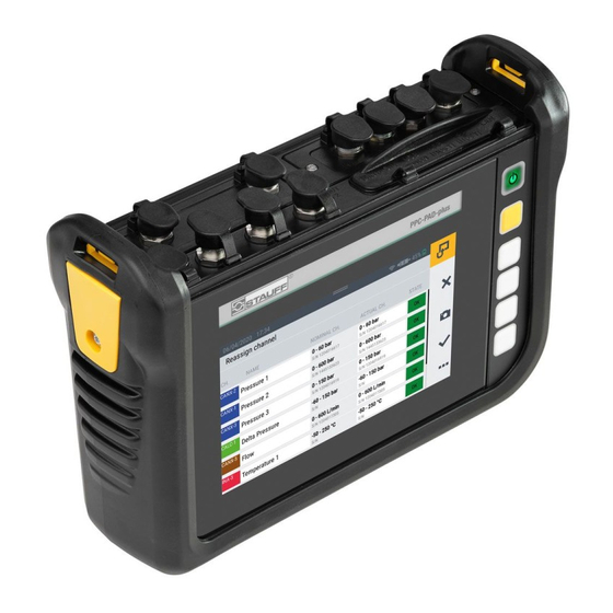
Product Description Intended Use STAUFF PPC-PAD-plus, subsequently referred to as "device", enables access to sensors used in hydraulic applications in machines and ve- hicles. The various connections can be used to compile, store, monitor and evaluate CAN bus data, digital or analog sensor signals for pres- sure, temperature, volume flows, frequencies, speeds, particles, water in oil, volumes and output, for example. -
Page 11: Conformity
Page 136. Equipment Supplied Check the parts included in the supply package prior to starting up the device. If anything is missing, please contact your sales outlet. ■ PPC-PAD-plus ■ Power adapter (110/240 V – 24 V / 3.750 mA) ■ Country adapters (EN, US, UK, AUS) ■... -
Page 12: Safety Information
Risk of fatal or severe personal injury. Probability of occurrence: very high. WARNING Risk of fatal or severe personal injury. Probability of occurrence: possible. CAUTION Risk of minor to moderate personal injury. Probability of occurrence: possible. IMPORTANT Risk of property damage. Probability of occurrence: possible. www.stauff.com... -
Page 13: Warnings
Type and source of the risk Consequences of failure to observe the warning ► Measures to avoid the risk IMPORTANT Type and source of the risk Consequences of failure to observe the warning ► Measures to avoid the risk www.stauff.com... -
Page 14: Basic Warnings
► If you are in doubt as to any possible risks, contact a doctor or the manufacturer of the medical device to check if the screening provided is adequate. www.stauff.com... - Page 15 ► Never immerse the device in water or other liquids. ► Never attempt to repair the device yourself. The device may only be repaired by STAUFF. ► Never clean the device with substances containing solvents. The device may only be cleaned in the way described in Section "Cleaning".
-
Page 16: Safety-Related Warnings
Safety Information Safety-Related Warnings Throughout this operating manual, warnings which relate to specific, in- dividual functional processes or activities are provided directly preced- ing the corresponding instructions. www.stauff.com... -
Page 17: Technical Personnel
Technical personnel must have read and understood the operating manual. Technical personnel must have access to the content of the operating manual at all times. www.stauff.com... -
Page 18: Design And Function
This chapter contains information on the design of the device and the functions provided. The connection ports, pin assignments and interfaces available on the device are described. INFORMATION Information on the input modules is provided in Chapter ""Input Mod- ules" on Page 26. www.stauff.com... -
Page 19: Overview
(power connection, CAN X, CAN Y, D-IN/D-OUT F1/F2) Input module A (option) Input module B (option) Communication ports (2 × USB Host, 1 × USB Device, LAN) and SIM card slot On/Off key Context-sensitive function keys Screen (touchscreen) Shock protection www.stauff.com... -
Page 20: Functions And Features
■ Various types of measurement and their representation ■ Module slots to extend system with input modules ■ LAN connection port ■ GPS ■ Wireless interfaces (option): Bluetooth LE, WLAN, LTE ■ Fold-out stand ■ VESA standard for wall installation www.stauff.com... -
Page 21: Connections
To connect a network cable More information on the sensor connection ports is available in the following chapters. INFORMATION Do not connect the device via the LAN and USB ports simultaneously when transmitting data to PPC-Analyze. This will prevent any distur- bance. www.stauff.com... -
Page 22: Stauff Can / External Can
STAUFF CAN / External CAN You can use the CAN X and CAN Y ports to connect the device via CAN BUS lines and additional Y-junctions to up to 24 STAUFF sensors (max. 24 channels ) with automatic sensor detection (STAUFF CAN). - Page 23 Page 90. INFORMATION It is not possible to mix operation on one CAN bus using sensors with automatic sensor detection (STAUFF CAN) and external sensors with- out automatic sensor detection (External CAN). IMPORTANT The internal terminating resistor of the CAN-Y is fixed. Do not switch the device to the bus via a stub.
-
Page 24: D-In/D-Out F1/F2
Refer to the following overview for the PIN assignment: Fig. 5 Connection port, D-IN/D-OUT F1/F2 PIN D-IN/D-OUT F1/F2 Digital-In+ Frequency signal 1 Digital-In GND Frequency signal 1 GND Digital-Out+ Frequency signal 2 Digital-Out GND Frequency signal 2 GND +Ub (+24 V +Ub (+24 V www.stauff.com... -
Page 25: Connection Ports - Input Modules
Input module, SLOT First slot for an input module Input module, SLOT Second slot for an input module Further information on the input modules available, the corresponding connections and PIN assignment is available in Chapter "Input Mod- ules" on Page 26. www.stauff.com... -
Page 26: Input Modules
Input Modules Input Modules This chapter provides information on the input modules available. INFORMATION The input modules can be obtained separately. To do this, contact your sales outlet. www.stauff.com... -
Page 27: Inserting The Input Module
2 Remove the dummy cover from the slot and keep it in a safe place. 3 Insert the input module (2) in the slot. 4 Tighten the two screws (1) hand-tight. Ä The input module is installed and ready to operate. Fig. 7 Insert the input module www.stauff.com... -
Page 28: Analog Input Module
Analog Input Module The analog input module is equipped with three analog connection ports, IN1-3, for sensors with automatic sensor detection (STAUFF an- alog) and an analog connection, IN4/5, for up to two external sensors without automatic sensor detection (e.g. standard industrial sensors). -
Page 29: Fig. 9 Pin Assignment, Analog Input Module
After connecting the sensors without sensor detection, complete the necessary settings for the electrical connection and expected signal ac- cording to the properties of the sensors connected. Refer to Chapter & "Input Modules A and B" on Page 98. www.stauff.com... -
Page 30: Can Input Module
CAN masters. The figure indicates the connection ports on the analog input module: Fig. 10 Can Input Module Pos. Designation Description CAN bus (CAN1xx) To connect sensors without automatic sensor detection CAN bus (CAN2xx) To connect sensors without automatic sensor detection www.stauff.com... -
Page 31: Fig. 11 Pin Assignment, Can Input Module
CAN Low After connecting the sensors without sensor detection, complete the necessary settings for the electrical connection and expected signal ac- cording to the properties of the sensors connected. Refer to Chapter & "Input Modules A and B" on Page 98. www.stauff.com... -
Page 32: Starting Up
Observe the following information regarding use of the integrated bat- tery: ► If the charge status of the integrated battery drops below a spe- cific value, the measurement in progress is stopped. The mea- sured values and user parameters are automatically saved. The device switches off automatically. www.stauff.com... -
Page 33: Switching The Device On And Off
1 When switched on, press and hold the On/Off key for at least 5 seconds. Ä The device is switched off. Alternatively: 1 When switched on, press the On/Off key. Ä The SHUT DOWN button appears in the display. 2 Press the SHUT DOWN button. Ä The device is switched off. www.stauff.com... -
Page 34: Connecting The Sensors
Restart the measurements in order to record data from sensors just connected. Measuring data from sensors which are disconnected while a mea- surement is in progress is recorded by the device to the moment of disconnection. www.stauff.com... -
Page 35: Using The Stand
The stand can be folded out to a maximum angle of 40°. Fig. 13 Using the fold-out stand 1 Pull the fold-out stand on the rear side of the device to the re- quired position. 2 Set the device down on a level surface. www.stauff.com... -
Page 36: Mounting The Device
Starting Up Mounting the Device If necessary, you can mount the device on a wall after assembling the VESA holder (100 mm × 100 mm) on the rear panel of the device. Fig. 14 Assembling the holder www.stauff.com... - Page 37 3 Screw the device using four retaining screws and an appropriate tool. Ä The device is mounted. INFORMATION The maximum screw-in depth for the retaining screws is 6 mm. The VESA holder and screws necessary for assembly (M4 metric) are included in the supply package. www.stauff.com...
-
Page 38: Operation
Select one of the four display options for the measurement view and define the type of measurement for your application accordingly. 6.1.1 Operating the Device The device is mainly operated by using the buttons provided on the www.stauff.com... - Page 39 It is also possible to use the touchscreen when wearing gloves appro- priate for the purpose. Function Keys The device is equipped with six function keys positioned beside the touchscreen. One function key is used to switch the device on and www.stauff.com...
- Page 40 Function On/Off key Function key (yellow) to start and stop measurements Four context-sensitive function keys Buttons The device displays the buttons appropriate for the current view. Tap your fingers directly on the buttons displayed on the screen to navigate www.stauff.com...
-
Page 41: Screen Design
A screen keyboard appears with which to enter digits and characters. Further information on the buttons available is provided in Chapter & "Screen Design" on Page 41. Screen Design This chapter contains information on the basic layout of the screen and the positions of the screen elements. www.stauff.com... -
Page 42: Fig. 15 Screen Layout
To initiate the main functions Button, Options To unhide/hide the options 6.2.1 Status Bar The status bar displays various symbols to indicate certain system states and general information such as date and time. The table below indicates the possible symbols: www.stauff.com... -
Page 43: Status Bar
Battery charge status as an icon Active connection to PPC-Analyze or online measurement in progress 6.2.2 Quick Start Menu You can open the Quick Start menu via the status bar. The Quick Start menu displays information and provides the option of defining settings. www.stauff.com... -
Page 44: Quick Start Menu
1 Swipe from the top screen edge downwards. Ä The Quick Start menu opens. 2 Swipe upwards over the QuickStart menu. Ä The Quick Start menu closes. Further information on setting WLAN connections is available in Chap- ter & "Connections" on Page 102. www.stauff.com... -
Page 45: Screen Keyboards
Open the Settings menu by tapping on the gearwheel symbol. 6.2.3 Screen Keyboards A screen keyboard appears in the display to enter texts and digits. The screen keyboard automatically appears when you select the cor- responding input field. The following keyboard is available to enter texts and digits: www.stauff.com... -
Page 46: Fig. 17 Screen Keyboard, Characters And Digits
INFORMATION The keyboard layout varies according to various languages and can be changed. The following keyboard layouts are available: QWERTZ, QWERTY, AZERTY. Refer to Chapter & "Device" on Page 106. The following keyboard is available to complete basic arithmetical op- erations: www.stauff.com... -
Page 47: Fig. 18 Screen Keyboard, Simple Arithmetic Operations
Operation Fig. 18 Screen keyboard, simple arithmetic operations The following keyboard is available to complete more advanced math- ematical calculations: Fig. 19 Screen keyboard, advanced mathematical calculations www.stauff.com... -
Page 48: Menu Area
The table below indicates the possible buttons: Symbol Function Switch to the main view Switch between measurement views Switch to the last menu option Create a screenshot of the current view Switch to the main menu Unhide/Hide the options Display information on the current measurement www.stauff.com... - Page 49 Operation Symbol Function Add an entry Edit a setting Record a measuring point ("Keystroke" presetting) Confirm current selection or adapted settings Discard current selection or adapted settings Zoom in on current view Zoom out from current view www.stauff.com...
-
Page 50: Options
The table below indicates the buttons possible in the File Manager: Fig. 21 Options menu in the File Manager Designation Description Copy Copy file(s) Move Move file(s) to a different folder/memory location Delete Delete file(s) Rename Rename the file(s) Search Search for file(s) www.stauff.com... -
Page 51: Resetting Values
3 Tap on the respective function to reset the corresponding value. Ä The value selected is reset. The selected function resets the values of all the channels. INFORMATION It is not possible to reset values when a measurement is in progress. www.stauff.com... -
Page 52: Measurement Views
Changing the Measurement View You can switch between the individual measurement views: 1 Tap on the button. Ä The next measurement view appears. It is possible to switch between the individual measurement views while a measurement is in progress. www.stauff.com... -
Page 53: List 6 View
This section displays the maximum and minimum measured values, bar graphs or the measuring range full scale value in various display combinations. Possible combinations: BAR- GRAPH, BARGRAPH + MAX, MIN + MAX, MIN + BARGRAPH, BARGRAPH + FS) Switch to the next screen display combination www.stauff.com... -
Page 54: List 12 View
This view enables you to follow twelve chan- nels in one view. If more than twelve channels are active, you can scroll through the list. Fig. 23 List 12 view Pos. Description Names of the active channels. Current measured values of the channels www.stauff.com... -
Page 55: Manometer View
Starting value for measuring range Current measured value Full scale (FS) value of measuring range Drag indicator for minimum and maximum measured value INFORMATION The yellow range in the manometer indicates the defined warning value, the red range the defined alarm value. www.stauff.com... -
Page 56: Trend Graph View
You can save the measurements in order to analyze the measured values using curve tools. Fig. 25 Trend graph view Pos. Description Name of the channel Current measured value of the channel Selected channel (increased line thickness) Trend graph line of the selected channel www.stauff.com... -
Page 57: Fig. 26 Curve Tools
(X/Y): Fig. 26 Curve tools 1 Tap on the button. Ä The options are displayed. 2 Tap on the Curve tools button. 3 Tap on the X/Y axis button and adapt the scaling. www.stauff.com... - Page 58 2 Tap with two fingers on the screen and drag the fingers towards each other. Ä The graph is reduced in size again. 3 Tap twice with a finger on the screen. Ä The graph is scaled to 100%. www.stauff.com...
-
Page 59: Analyzing The Measurements
Cursor A of the selected channel INFORMATION The figure displays the trend graph view of a stored measurement with active curve tools. When a measurement is in progress, the trend graph view deviates because the curve tools are not available. www.stauff.com... -
Page 60: Fig. 28 Curve Tools
Jump to MAX The cursor springs to the maximum value of the selected channel Cursor ON/OFF Unhide or hide the cursor X/Y axis Adjust the scaling of the axes 4 Tap on the appropriate button. Ä The function selected is performed. www.stauff.com... - Page 61 The following information appears on the cursor: ■ Name of the channel ■ Time of measurement ■ Measured value You can select various channels and use the cursor to complete evalu- ations of the graph curves. www.stauff.com...
-
Page 62: Edit Channels
The functions can be used to hide or activate/deacti- vate individual channels. 1 Tap on the button. 2 Tap on the Edit channels button. Ä The window in which to edit the channels opens. Fig. 29 Edit channels www.stauff.com... - Page 63 4 Define the parameters as required. 5 Tap on the button to activate the setting. Ä You have now edited the channel successfully. *This option was not available at the time of the manual going to print. www.stauff.com...
-
Page 64: Fig. 30 Edit Channels, Adjust Parameters
You can define the number of decimal places, the unit and the mini- mum and maximum alarm and warning values for each channel. If a channel reaches a defined alarm or warning value, the current mea- sured value is displayed in color in the bar graphs. www.stauff.com... -
Page 65: Measurement Status
Recording of the measured data begins according to the measuring method selected, either immediately or after triggering one or several triggers. The current runtime of the measurement is displayed underneath the Start/Stop button. 2 Tap on the Start/Stop button. Ä The measurement is stopped. www.stauff.com... -
Page 66: Measuring Methods
You can switch between the measuring methods. 1 Tap on the measuring method menu option. 2 Tap on the measuring method required. Ä The measuring method selected is displayed. INFORMATION The button displays the name of the measuring method selected (e.g. Start/Stop). Fig. 31 Measuring methods www.stauff.com... -
Page 67: Start/Stop
In this case, the Min and Max values are also compared and the highest and lowest measured value are transferred to the Min and Max value respectively. INFORMATION The Min and Max values are not lost but are saved, even in the case of long-term measurements. www.stauff.com... -
Page 68: Data Logger
If this option is activated, the defined memo- ry area is continuously overwritten by current measured data Recording MIN/MAX If this option is activated, the Min and Max measured values are also recorded in addi- tion to the current measured value www.stauff.com... -
Page 69: Fig. 32 Data Logger, Settings
Operation Fig. 32 Data logger, settings The file size expected and maximum storage time for the measurement are calculated and displayed according to the applicable, defined pa- rameters. www.stauff.com... -
Page 70: Point Measurement
After selecting the Point measurement measuring method, the device displays a predefined trigger to start the measurement. 1 Tap on the button. Ä The configuration window to select the trigger opens. 2 Select a trigger source according to your application. www.stauff.com... -
Page 71: Fig. 33 Point Measurement), Settings
Measurement is started by tapping on the Start/Stop button. The de- vice waits for the defined trigger to be triggered. Recording of a mea- sured point starts when the defined trigger is triggered. Measurement is stopped by tapping on the Start/Stop button. www.stauff.com... -
Page 72: Trigger
When the option is activated, the measurement is started again the next time the trigger is trig- gered after automatic storage of the previous measurement Ring buffer If this option is activated, the defined memory area is continuously overwritten by current measured data www.stauff.com... -
Page 73: Fig. 34 Trigger, Settings
Measurement is started on transition of the digital signal from Low to High Channel warning Recording of a measuring point if defined warning value values occur Channel alarm Recording of a measuring point if defined alarm value values occur Fig. 34 Trigger, settings www.stauff.com... -
Page 74: Fig. 35 Trigger, Settings
Recording of a mea- sured value starts when the defined trigger is triggered. Measurement is stopped when the defined storage time has expired or the Start/Stop button is tapped. Fig. 35 Trigger, settings www.stauff.com... -
Page 75: Trigger Logic
The following triggers are available for the start conditions: Trigger A Trigger B Trigger C Trigger D Level Level Level Level Window Window Window Window Time Time External External External External Keystroke Duration Channel Channel warning value warning value Channel alarm Channel alarm value value www.stauff.com... - Page 76 Measurement is started/stopped when defined value alarm values occur Duration Measurement stops after a defined time period has expired INFORMATION Please note that the D-IN connection must be activated for the exter- nal trigger. Refer to Chapter & "D-IN/D-OUT F1/F2" on Page 94. www.stauff.com...
-
Page 77: Fig. 36 Trigger Logic, Settings
Operation The measurement is started after one or two defined triggers are trig- gered. The measurement is stopped after one or two defined triggers are trig- gered or tapping on the Start/Stop button. Fig. 36 Trigger logic, settings www.stauff.com... -
Page 78: Fast Measurement
When the option is activated, the measurement is started again the next time the trigger is trig- gered after automatic storage of the previous measurement Ring buffer If this option is activated, the defined memory area is continuously overwritten by current mea- sured data www.stauff.com... - Page 79 Measurement is started when defined warning value warning values occurs Channel alarm Measurement is started when defined value alarm values occur INFORMATION Please note that the D-IN connection must be activated for the exter- nal trigger. Refer to Chapter & "D-IN/D-OUT F1/F2" on Page 94. www.stauff.com...
-
Page 80: Fig. 37 Fast Measurement, Settings
Operation Measurement is started when the trigger is triggered and stopped when the defined storage time has expired or the Start/Stop button is tapped. Fig. 37 Fast measurement, settings www.stauff.com... -
Page 81: Completing A Measurement
Project Container (SPC) at the defined storage location. Further information is available in Chapter & "Project Management" on Page 82. You can access the measured data via the File Manager in order to complete evaluations. Further information is available in Chapter & "File Manager" on Page 88. www.stauff.com... -
Page 82: Project Management
■ Media: PDF files, screenshots, photos, videos* etc. These settings can be used as templates for new measuring tasks. An SPC can contain and manage several different measuring tasks. *This option was not available at the time of the manual going to print. www.stauff.com... -
Page 83: Fig. 38 Spc (Service Project Container)
Please note that the standard SPC is essential for correct functioning of the device and cannot be deleted. SPCs and the related files can be edited or fully deleted via the File Manager. Further information on editing and deleting files is available Chapter & "File Manager" on Page 88. www.stauff.com... -
Page 84: Creating An Spc (Service Project Container)
2 Set the measurement view required. Further information is avail- able in Chapter "Edit Channels" on Page 62. 3 Open the options and tap on the Save Template as button. Fig. 39 Create an SPC (Service Project Container) (1) Ä The Save template window opens. www.stauff.com... -
Page 85: Fig. 40 Create An Spc (Service Project Container)
Create an SPC (Service Project Container) (2) Ä The Select storage location window opens. INFORMATION If the storage location selected already contains SPCs, an overview of the SPCs opens. If necessary, select an existing SPC or tap on the button to add a new SPC. www.stauff.com... -
Page 86: Fig. 41 Create An Spc (Service Project Container)
10 Tap on the button to save the Service Project Container (SPC). Ä The Save template window opens again. 11 Tap on the button to save the template. Ä The new template and new Service Project Container (SPC) have now been created. www.stauff.com... -
Page 87: Menu
To manage all the connections (e.g. network, cloud) Refer to Chapter & "Connections" on Page 102 Settings To setup the device (e.g. screen brightness, volume, battery). Refer to Chapter & "Settings" on Page 105 Use the button to return to the measurement view. www.stauff.com... -
Page 88: File Manager
The tiles of the storage media provide the following information: ■ The total number of Service Project Containers (SPC) stored ■ The total number of templates stored ■ The total number of measurements stored ■ An overview of the occupied and total number of storage locations www.stauff.com... -
Page 89: Managing Files
After selecting a storage medium, an overview of all the Service Project Containers (SPC) and other data stored on the storage medium ap- pears. Fig. 44 Manage files INFORMATION Please note that only files from the SPCs area can be edited. Files from the Other files area cannot be edited. www.stauff.com... -
Page 90: Sensors
The Menu is comprised of a series of tiles which provide a preview of the settings contained in them. Each tile can also be used as a button to open the corresponding submenu. If no input modules are imple- mented, the tiles (A, B) are grayed out. Fig. 45 Sensors www.stauff.com... - Page 91 Information on the connection port, setting F1/F2 and parameterization Calculating Setting of the four calculation channels channels IM CAN/SAEJ Setup and parameterization of the connection ports on input module B IM standard Setup and parameterization of the connection ports on input module A www.stauff.com...
-
Page 92: Can X
Current operating mode Baud rate Current Baud rate Up to 24 STAUFF sensors (max. 24 channels) can be connected to the CAN X port. Other setting adjustments are also possible. 6.10.2 CAN Y The CAN Y tile displays the following information:... -
Page 93: Fig. 46 Can-Y Connection Port, Settings
Define the parameters for the selected channel according to your ap- plication. Fig. 46 CAN-Y connection port, settings For further information, refer to the & Technical Data related to the sensors connected. INFORMATION When External CAN operating mode is active, the settings may only be defined by properly trained technicians. www.stauff.com... -
Page 94: D-In/D-Out F1/F2
D-OUT State (0/1) Operating mode D-OUT Setup the selected operating mode according to your application. Fig. 47 Connection D-IN/D-OUT F1/F2, settings Further information is provided on the following pages and in the & Technical Data related to the sensor connected. www.stauff.com... - Page 95 Select between the following combinations as the start condition: ■ Condition A ■ Conditions A and B ■ Conditions A or B The following triggers are available for the conditions: Condition A Condition B Level Level Window Window Time External External Channel warning value Channel alarm value www.stauff.com...
- Page 96 The following methods are available in the Switch function area: Designation Description NCLS (Opener) 0 = Active-Low: Output is < 0.2 V (closed) 1 = Active-High: Output is dead (open) NOPN (Closer) 1 = Active-High: Output is dead (open) 0 = Active-Low: Output is < 0.2 V (closed) www.stauff.com...
- Page 97 The following measuring methods are available for the combined two- channel connection: Designation Description Frequency Measurement of the frequency Rotational speed Measurement of the rotational speed Flow rate Measurement of the flow rate Define the settings according to your application. www.stauff.com...
-
Page 98: Input Modules A And B
Further options are available for setup and configuration according to the input module and connections available. For further information, refer to the & Technical Data related to the sensors. Fig. 48 Input module, settings www.stauff.com... -
Page 99: Fig. 49 Pin Assignment Of Sensors Without Sensor Detection
INFORMATION Further information on connecting sensors without sensor detection via an adapter and the relevant parameters for configuration is avail- able in the manual supplied with the respective sensor. www.stauff.com... -
Page 100: Calculating Channels
A condition is at least one pressure channel and one flow channel Power 2 To calculate power through differential pressure A condition is two pressure channels and one flow channel Moving average To calculate a floating average for a channel www.stauff.com... -
Page 101: Fig. 50 Calculating Channels
In addition to the calculation types available, freely editable equations can be created with up to three variable channels. The formula library contains standard formulas and new formulas can be saved in the user formula library. Define the calculation types according to your application. Fig. 50 Calculating channels www.stauff.com... -
Page 102: Connections
Each tile can also be used as a button to open the corresponding submenu. Fig. 51 Connections Pos. Designation Description Wireless & Net- Settings for wifi, LAN, Bluetooth, mobile works communication, proxy server Remote desktop Activate/Deactivate and settings for remote access www.stauff.com... -
Page 103: Wireless & Networks
Bluetooth Status of the Bluetooth connection Mobile phone number Status of the mobile communication The submenu enables you to define settings for wifi and LAN connec- tions and to connect or disconnect the respective connection: Fig. 52 Wireless & Networks www.stauff.com... -
Page 104: Remote Desktop
Fig. 53 Remote desktop INFORMATION The IP address is automatically displayed when the LAN or wifi con- nection is active. If both connections are active, only the IP address of the LAN connection is displayed. www.stauff.com... -
Page 105: Settings
Fig. 54 Settings Pos. Designation Description Device Settings on the device User User information System Update the device firmware, create a backup Information Information on the device Service Link to the service and manufacturer websites www.stauff.com... -
Page 106: Device
Time until the display is dimmed Tones Volume of the device for various notifications Position determina- Switch the GPS on and off, select the system tion for GPS Language Languages Time/Date Time and date Keyboard QWERTZ / QWERTY / AZERTY www.stauff.com... -
Page 107: Fig. 55 Device
Operation Fig. 55 Device www.stauff.com... -
Page 108: User
The menu contains further information and options to edit the informa- tion. INFORMATION Information is voluntary. All the functions on the device can be used even without this information. To improve assignment, the name entered is added when a measure- ment is saved. Fig. 56 User www.stauff.com... -
Page 109: System
Read out and update the firmware version Information on completing a data backup is available in Chapter & "Creating a Backup" on Page 112. Information on resetting the device is available in Chapter & "Reset- ting the Device to its Default Settings" on Page 118. Fig. 57 System www.stauff.com... -
Page 110: Service
Operation 6.12.4 Service The Service tile displays links to the manufacturer's website. www.stauff.com... -
Page 111: Information
Name, serial number, order code, hardware version, firmware version, next calibration Memory Internal memory, USB1, USB2, network drive, cloud Battery Capacity, voltage, current, battery temperature, remaining charge time, remaining operating time, number of charge cycles User manual Operating manual Fig. 58 Information www.stauff.com... -
Page 112: Creating A Backup
1 Connect a storage medium (e.g. USB stick) to save the data. 2 Tap on the button. 3 Navigate to the Settings > System > Save & Reset menu op- tion. 4 Tap on the Create backup button. www.stauff.com... - Page 113 ► Before starting the process, ensure that the battery is charged to at least 50% or the device is connected to the main power via the power adapter. 6 Tap on the button. Ä The backup is performed. The process may take a few min- utes. www.stauff.com...
-
Page 114: Restoring A Backup
1 Connect the storage medium (e.g. USB stick) which contains the data backup. 2 Tap on the button. 3 Navigate to the Settings > System > Save & Reset menu op- tion. 4 Tap on the Restore backup button. www.stauff.com... - Page 115 ► Before starting the process, ensure that the battery is charged to at least 50% or the device is connected to the main power via the power adapter. 7 Tap on the button. Ä The data restoring process is performed. The process may take a few minutes. www.stauff.com...
-
Page 116: Troubleshooting
If you find no solution to your problem in this user manual, contact the relevant sales outlet. IMPORTANT Risk of material damage through improperly performed repair work. ► Never open the device! ► Never attempt to perform repair work yourself. ► In the event of defects, return the device to the manufacturer! www.stauff.com... -
Page 117: Restarting The Device
► Only initiate a restart of the device when it is absolutely necessary. 1 Press the On/Off switch and yellow function key simultaneously for approx. 3 seconds. Ä The device is switched off. 2 Press the On/Off key. Ä The device starts up again. Fig. 59 Restarting the device www.stauff.com... -
Page 118: Resetting The Device To Its Default Settings
IMPORTANT All the settings and parameters are returned to their default settings following a reset. 1 Tap on the button. 2 Navigate to the Settings > System > Save & Reset menu op- tion. 3 Tap on the Reset device to default settings button. www.stauff.com... - Page 119 50% or the device is connected to the main power via the power adapter. 4 Tap on the button to confirm the process. Ä The device is reset to the default settings. The process may take a few minutes. www.stauff.com...
-
Page 120: Updating The Firmware
3 Tap on the Check for update button. Ä The device searches for a firmware version update. Ä If there is no firmware update available, a system message appears. The current version number appears in the Update available field. 4 Tap on the Update available field. www.stauff.com... - Page 121 6 Wait until the process has finished. Ä The device restarts several times during the process. Ä When the process has been completed, the corresponding message appears in the display. Ä The latest version of the firmware is now installed on the de- vice. www.stauff.com...
-
Page 122: Packaging And Transporting
According to the currently applicable transport regulations regarding lithium-ion batteries, the respective devices or their packaging must be specially identified for transport. ► Contact your sales outlet prior to dispatch. ► Only dispatch the device in packaging which has been appropri- ately identified on the outside. www.stauff.com... -
Page 123: Cleaning And Maintenance
The device is maintenance-free for the user and must not be repaired by the user. Maintenance work is not necessary on the device within the scope of the intended use. The device must be recalibrated after a longer time in use. Contact your sales outlet in this case. www.stauff.com... -
Page 124: Repairing
■ Detailed description of the fault IMPORTANT Risk of material damage through improperly performed repair work. ► Never open the device! ► Never attempt to perform repair work yourself. ► In the event of defects, return the device to STAUFF! www.stauff.com... -
Page 125: Disposal
► Only dispatch the device in packaging which has been appropri- ately identified on the outside. ► Contact your sales outlet prior to dispatch. Any further questions? If you have any further questions, please contact your sales outlet. www.stauff.com... -
Page 126: Technical Data
This chapter contains information on the technical data of the device and input modules available. 11.1 Device Model Device Connections Sensors Channels Scanning rate PPC-PAD-plus 2 CAN bus 24 CAN X >1 ms 24 CAN Y >1 ms 1 D-IN 1 D-IN 1 ms... -
Page 127: Power Supply (External)
3350 mAh Battery power duration >6 h With 24 sensors, 20 mA per sensor 11.3.3 Memory Designation Property Main processor I.MX6 Internal memory 12 GB internal SD card (approx. 250 measurements) Measured value storage 16,000,000 data points / measurement www.stauff.com... -
Page 128: Inputs
PIN 4 and PIN 5 CAN Y 120 Ω terminating resistor be- No galvanic separation tween PIN 4 and PIN 5 Baud rate (STAUFF CAN) 500 kBit/s Baud rate (external CAN) 10, 20, 50, 125, 250, 500, 800, Only at CAN-Y 1000 kBit/s Sensors, CAN X Max. -
Page 129: Interfaces
2.400 – 2.4835 GHz (IEEE 802.11 b/g/n) in 13 channels Wifi transmission rate IEEE 802.11b: to 11 MBit/s IEEE 802.11g: to 54 MBit/s Wifi transmission power 20 mW at 2.400 – 2.4835 GHz Wifi encryption WPA, WPA2. WEP64/128, PEAP www.stauff.com... -
Page 130: Analog Input Modules
Housing material ABS/PC Housing sealing Type of protection IP65 When installed Ambient temperature -10 – +50 °C Storage temperature -20 – +60 °C 11.6.1 Connections, STAUFF Sensors Designation Properties Description Number Plug 5-pin, ODU For STAUFF sensors Inputs INx-1, INx-2, INx-3 Analog... -
Page 131: Can Input Module
1000 kBit Sensors, CAN1xx Max. 24 Sensors, CAN2xx Max. 24 Scanning rate, P-channel, 1 ms = 1,000 measured values/s Housing material ABS/PC Housing sealing Type of protection IP65 When installed Ambient temperature -10 – +50 °C Storage temperature -20 – +60 °C www.stauff.com... -
Page 132: Appendix
Appendix Appendix This chapter contains information on the device models available, the appropriate accessories, technical data and certificates. 12.1 Accessories Order code Description PLUG-PPC-PAD-PLUS-AUX-M12A/5 AUX-Adaptor Power-Supply-PPC-PAD-PLUS-MULTI Power Supply Carry-strap-PPC-PAD-PLUS Carry strap 12.2 Technical Standards Standard EN61326-1:2013 EN 55011:2009 EN 61000-3-2:2014 / -3:2013 EN 61000-4-2:2009 / -3:2006 / -4:2012 / -5:2014 / -6:2014 / -11:2004 ETSI EN 301 489-1 V2.1.1... -
Page 133: Dimensional Drawings
Appendix 12.3 Dimensional Drawings www.stauff.com... - Page 134 Appendix www.stauff.com...
- Page 135 Appendix www.stauff.com...
-
Page 136: Rating Plate
12.5 Certificates The basic certificates and Declaration of Conformity are provided for the device in the Settings > Information > Device menu option. INFORMATION Information on the approval tests can be obtained from your sales outlet. www.stauff.com... - Page 137 Appendix www.stauff.com...
-
Page 138: List Of Figures
Appendix 12.6 List of Figures Fig. 1 STAUFF PPC-PAD-plus Fig. 2 Overview Fig. 3 Connections Fig. 4 Connection port, CAN X / CAN Y Fig. 5 Connection port, D-IN/D-OUT F1/F2 Fig. 6 Connection port, input module Fig. 7 Insert the input module Fig. 8 Analog input module Fig. 9 PIN assignment, analog input module Fig. 10... - Page 139 Input module, settings Fig. 49 PIN assignment of sensors without sensor detection Fig. 50 Calculating channels Fig. 51 Connections Fig. 52 Wireless & Networks Fig. 53 Remote desktop Fig. 54 Settings Fig. 55 Device Fig. 56 User Fig. 57 System Fig. 58 System Fig. 59 Information Fig. 60 Restarting the device www.stauff.com...
- Page 140 Germany Walter Stauffenberg GmbH & Co. KG STAUFF products and services are globally available through wholly- owned subsidiaries and a tight network of authorised distributors and Im Ehrenfeld 4 58791 Werdohl representatives in all major industrial regions of the world.
Need help?
Do you have a question about the PPC-PAD-plus and is the answer not in the manual?
Questions and answers