
Subscribe to Our Youtube Channel
Related Manuals for Toshiba RBM-Y1801FU4PE


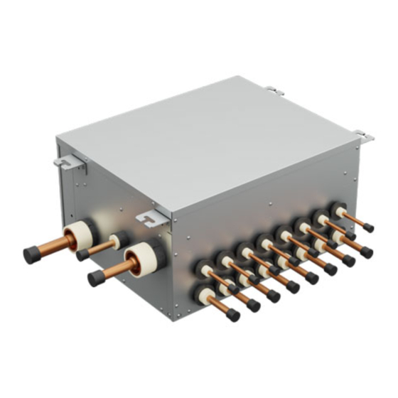
Summary of Contents for Toshiba RBM-Y1801FU4PE
- Page 1 Installation Manual Flow Selector unit Multi-port type RBM-Y1801FU4PE RBM-Y1801FU8PE RBM-Y1801FU12PE English...
-
Page 2: Table Of Contents
Flow Selector unit Multi-port type (hereafter "Flow Selector unit") Thank you very much for purchasing TOSHIBA Super Heat Recovery Multi Advance (SHRM-A) Air conditioner. Please read this manual carefully before using your Flow Selector unit. • When installing an indoor or outdoor unit, follow the Installation Manual supplied with the unit. -
Page 3: Accessory Parts And Parts To Be Procured Locally
PRECAUTIONS FOR SAFETY Accessory parts and Parts to be procured locally Accessory parts • Ensure that all Local, National and International regulations are satisfi ed. Q’ty RBM-Y1801 Part name Shape Usage FU4PE FU8PE FU12PE • Read this “PRECAUTIONS FOR SAFETY” carefully before This manual for installer. - Page 4 Meanings of symbols in this manual This mark is for R32 refrigerant These safety cautions describe important matters concerning only. Refrigerant type is written on safety to prevent injury to users or other people and damages to nameplate of outdoor unit. property.
- Page 5 • To avoid personal injury (with sharp edges), be careful when WARNING handling parts. • Ask an authorized dealer or qualifi ed installation • Perform installation work properly according to the professional to install/maintain the air conditioner. Installation Manual. Inappropriate installation may result in water leakage, electric Inappropriate installation may result in water leakage, electric shock or fi...
-
Page 6: Selection Of Installation Place
SELECTION OF INSTALLATION PLACE • Use the specifi ed wires for wiring connect the terminals securely fi x. To prevent external forces applied to the terminals from CAUTION affecting the terminals. Do not install the air conditioner at place where combustible gas may leak. If gas leaks is collected at surrounding the unit, the production of fi... - Page 7 Installation under high-humidity atmosphere <Installation space> (Unit : mm) In some cases including the rainy season, especially inside of the ceiling may become high-humidity atmosphere. 1. Installation to inside of the ceiling with tiles on the roof Bolt size : M10 or Ø3/8 (fi...
-
Page 8: Installation Of Flow Selector Unit
INSTALLATION OF FLOW SELECTOR Installation of hanging bolt Use M10 hanging bolts (4 pcs, locally procured). UNIT Matching to the existing structure, set pitch according to size in the unit external view as shown below. New concrete slab Install the bolts with insert brackets or anchor bolts. WARNING Rubber Install the unit securely in the place to suffi... -
Page 9: Installation Of Battery Kit
P.C. board, a Battery kit for it is required. Refer to the Installation Manual of the outdoor unit for details. Control Box • Do not connect anything except TOSHIBA Battery kit. • This kit includes a nickel-metal hydride battery (NiMH). For your safety, please read Instruction Manual in Suction gas pipe Battery kit carefully and handle it with care. -
Page 10: Refrigerant Piping
REFRIGERANT PIPING Switch only the No. 4 DIP switch of SW03 to ON Battery kit 1 2 3 4 Screw SW03 WARNING (Accessory of Battery kit) If refrigerant gas has leaked during the installation work, ventilate the room immediately. If the leaked refrigerant gas comes in contact with fi re, noxious gas may be generated. After the installation work, confi... - Page 11 Pipe connecting process • Be sure to connect the indoor unit to port No. 1 of the Flow Selector unit. (Figure 1) • Allows the concatenation of two neighboring ports.(Connecting pipes are arranged locally.) (Figure 2) • Connect the pipes. (Be sure to use port No.1) •...
- Page 12 Airtight test/Air purge, etc. Figure 5 For airtight test, air purge, addition of refrigerant, and gas leak check, follow the Installation Manual attached to Incorrect the outdoor unit. Outdoor unit REQUIREMENT Flow Selector unit Multi-port type Be sure to use the tool such as charge hose exclusive to R32 or R410A. Piping Do not turn on the power until the airtight test and the vacuuming have fi...
-
Page 13: Electrical Connection
ELECTRICAL CONNECTION Communication wiring • 2-core with non-polarity wire is used for wiring of the communication wiring. CAUTION • Wire size : 0.5 mm² to 2.0 mm² • Up to 300 m (L1 + L2 + L3 + L4) • If incorrect / incomplete wiring is carried out, it will cause an electrical fi re or smoke. •... - Page 14 Connecting power supply wire and communication wires See the fi gure on the left for connecting wires to the terminal. Screw (upper side) Earth wire Communication wire Power supply wire Communication wires Communication wiring Screw (upper side) Terminal block for remote controller wiring of indoor unit Screw...
- Page 15 144 / 9 Moo 5, Bangkadi Industrial Park, Tivanon Road, Tambol Bangkadi, Amphur Muang, Pathumthani 12000, Thailand 1143012099...
Need help?
Do you have a question about the RBM-Y1801FU4PE and is the answer not in the manual?
Questions and answers