Table of Contents
Advertisement
User Notice ........................................................................................................................................................................... - 3 -
Safety Notes .................................................................................................................................................................... - 3 -
Copyright ......................................................................................................................................................................... - 4 -
Special Features ............................................................................................................................................................... - 4 -
Specifications .................................................................................................................................................................. - 5 -
Warranty & Service ......................................................................................................................................................... - 5 -
Device Introduction ............................................................................................................................................................. - 6 -
Parts & Interface Introduction ......................................................................................................................................... - 6 -
Standard Accessories ....................................................................................................................................................... - 7 -
Optional Accessories ....................................................................................................................................................... - 7 -
Buttons Function & Icons Description ............................................................................................................................ - 8 -
Connection for Charger ...................................................................................................................................................... - 9 -
The Power Input Ground Cannot be Connected with the Output Ground ....................................................................... - 9 -
Connection for Channel Asynchronous Mode ................................................................................................................. - 9 -
Connection for Channel Synchronous Mode ................................................................................................................... - 9 -
Charge/Discharge Setup & Use ........................................................................................................................................ - 10 -
Power Supply Setup ...................................................................................................................................................... - 10 -
Memory Add & Delete & Edit ...................................................................................................................................... - 11 -
Run Program for Charger .............................................................................................................................................. - 12 -
Program Running Status ................................................................................................................................................ - 13 -
Modifying Running Program's Parameters ................................................................................................................... - 14 -
Stop Running Program .................................................................................................................................................. - 14 -
Error Messages .............................................................................................................................................................. - 14 -
Monitor Settings ............................................................................................................................................................ - 14 -
Internal Resistance Measurement .................................................................................................................................. - 14 -
USB & SD Card Use ..................................................................................................................................................... - 15 -
Setup of Different Batteries ........................................................................................................................................... - 15 -
LiPo/LiIo/LiFe/LiHV/LTO/NiZn /User Setup ............................................................................................................ - 16 -
LiPo/LiIo/LiFe/LiHV/LTO/NiZn/User Charge Setup ........................................................................................... - 16 -
LiPo/LiIo/LiFe/LiHV/LTO/NiZn/User NON-Balance Charge Setup ............................................................. - 16 -
LiPo/LiIo/LiFe/LiHV/LTO/NiZn/User Balance Charge Setup ....................................................................... - 17 -
LiPo/LiIo/LiFe/LiHV/LTO/NiZn/User Charge Advanced Setup .................................................................... - 18 -
LiPo/LiIo/LiFe/LiHV/LTO/NiZn/User Safety Setup ...................................................................................... - 18 -
LiPo/LiIo/LiFe/LiHV/LTO/User Storage Setup.................................................................................................... - 18 -
LiPo/LiIo/LiFe/LiHV/LTO/NiZn/User Discharge Setup ...................................................................................... - 19 -
Regenerative To Input ..................................................................................................................................... - 19 -
Regenerative To Channel ................................................................................................................................ - 19 -
LiPo/LiIo/LiFe/LiHV/LTO/NiZn/User Discharge Advanced Setup ............................................................... - 20 -
LiPo/LiIo/LiFe/LiHV/LTO/NiZn/User Discharge Safety Setup ..................................................................... - 20 -
LiPo/LiIo/LiFe/LiHV/LTO/NiZn/User Cycle Setup ............................................................................................. - 20 -
LiPo/LiIo/LiFe/LiHV/LTO/User Only Balance Feature ....................................................................................... - 20 -
NiMH/NiCd Battery Setup ......................................................................................................................................... - 22 -
NiMH/NiCd Battery Charge Setup ....................................................................................................................... - 22 -
458DUO User's Manual (V1.0.0)
Dual Balance Charger/Discharger/DC Power
Index
- 1 -
458DUO
Advertisement
Table of Contents

Related Manuals for iCharger 458DUO


Summary of Contents for iCharger 458DUO
-
Page 1: Table Of Contents
458DUO Dual Balance Charger/Discharger/DC Power 458DUO User's Manual (V1.0.0) Index User Notice ................................... - 3 - Safety Notes ..................................- 3 - Copyright ..................................- 4 - Special Features ................................- 4 - Specifications .................................. - 5 - ... - Page 2 Log Files Manage ..............................- 30 - Servo Test ................................- 30 - Pulse Measurement ............................... - 32 - Junsi Console for 458DUO..............................- 33 - Firmware Upgrades ................................- 34 - Firmware Upgrades via Junsi Console .......................... - 34 - ...
-
Page 3: User Notice
Please read the entire Manual completely before using, to make sure you can use this device properly and more safely. 458DUO is a dual port charger, but this does not mean you can charge/discharge any configuration of the two sets of batteries! You must follow these rules: two battery packs without any external electrical connections, otherwise they could permanently damage the charger or batteries. -
Page 4: Copyright
23 458DUO has protection for reversed polarity (input or output), input voltage/current, battery temperature, charging capacity, overrun time and maximum power etc. 24 Supports upgrading the hardware program by USB port or SD card. 458DUO also supports the “Junsi Console” software and can display, plot and analyze the charge and discharge data by it. -
Page 5: Specifications
458DUO Dual Balance Charger/Discharger/DC Power Specifications Input voltage range: 10—49VDC Maximum Output voltage: 40VDC Maximum input current limit: 70A(Channel 50A) Maximum charge/discharge current: 70A(Channel 45Ax2) Maximum charge power capacity: 2200W(Channel 1600Wx2) Maximum discharge power capacity: 140W(Channel 80Wx2) Maximum regenerative discharge power capacity:... -
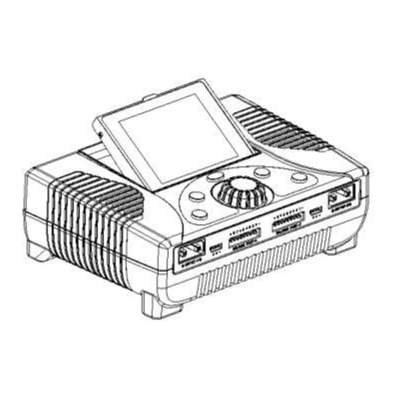
Page 6: Device Introduction
458DUO Dual Balance Charger/Discharger/DC Power Device Introduction Parts & Interface Introduction 01) Power input port 02) USB Type-C & PD 03) Fans 04) SD card slot 05) CH-1 Output port 06) CH-1 Multi-function port 07) CH1 Balance port 08) CH-2 Output port... -
Page 7: Standard Accessories
458DUO Dual Balance Charger/Discharger/DC Power Standard Accessories User’s manual & Software Input cable Output plug CD-ROM cd-rom resources download: EC8/10AWG/600mm XT90H-F: 2pcs http://www.hillrc.com/cd_rom.zip Optional Accessories Temperature sensor Output cable 350mm XT90/12AWG/300mm Balance connector conversion board Balance wire for balance board... -
Page 8: Buttons Function & Icons Description
458DUO Dual Balance Charger/Discharger/DC Power Buttons Function & Icons Description Please refer to below chart for button functions Operation Function Symbols Initial interface: Enter CHANNEL SELECTION Click the rotary switch <> Other interface: Confirm function or enter submenu Press the rotary switch MEMORY SELECTION interface: Enter Management Menu <>... -
Page 9: Connection For Charger
458DUO Dual Balance Charger/Discharger/DC Power Connection for Charger The Power Input Ground Cannot be Connected with the Output Ground 1. The input of power lead cannot be connected directly to the output (left picture), and the voltage of the input power supply cannot have large instantaneous fluctuations, otherwise the charger will be damaged. -
Page 10: Charge/Discharge Setup & Use
458DUO Dual Balance Charger/Discharger/DC Power Charge/Discharge Setup & Use 458DUO can charge/discharge LiVH, LiPo, Lilo, LiFe, LTO, NiZn, NiMH, NiCd, Pb batteries, this manual will explain and introduce in detail the charger’s features, setup and use. Power Supply Setup The charger boots automatically when the power is turned on and the initial interface will display LOGO, charger relevant information, power source and message etc. -
Page 11: Memory Add & Delete & Edit
458DUO Dual Balance Charger/Discharger/DC Power Memory Add & Delete & Edit Click <STOP/START-x> button on the initial interface to pop up the MEMORY SELECT interface. Memory No. Memory Name Running times Except 10 built-in memorys, there are 54 customized ones can be added. All memorys include three types as below:... -
Page 12: Run Program For Charger
458DUO Dual Balance Charger/Discharger/DC Power Channel Mode: Asynchronous (default); Synchronous Auto save before the program runs: if ticking, the modified parameters will be saved automatically; default: ticking Run Counter: 0-999; default: 0 Log Interval: 0.5-60Sec; default: 1Sec Log save to SD card: If ticking, the Log will be saved to SD card 1. -
Page 13: Program Running Status
458DUO Dual Balance Charger/Discharger/DC Power After selecting the program to run, press <> to pop upconfirmation window, as below: Click “Yes” to run the program, click “No” to cancel. Program Running Status Running program name Battery type Running channel status... -
Page 14: Modifying Running Program's Parameters
Internal Resistance Measurement 458DUO can measure the internal resistance of the battery but the data accuracy is not high. It’s greatly affected by the number of battery strings, detection current and other factors. During charging or discharging, it automatically started the... -
Page 15: Usb & Sd Card Use
USB icon will light up on the lower right corner of the screen when the 458DUO connects with computer normally. The SD icon will light up on the lower right corner of the screen when the SD card is inserted. If 458DUO connects with the USB without running a program, the new added U disk can be found on the "My Computer”... -
Page 16: Lipo/Liio/Life/Lihv/Lto/Nizn /User Setup
458DUO Dual Balance Charger/Discharger/DC Power LiPo/LiIo/LiFe/LiHV/LTO/NiZn /User Setup After adding a program, it will switch to LiPo/LiIo/LiFe/LiHV/LTO/NiZn/User battery in Type option on the MEMORY SETUP interface, and set the number of cells and capacity, if there is no setting for the number of cells, the charger will set Auto by default. -
Page 17: Lipo/Liio/Life/Lihv/Lto/Nizn/User Balance Charge Setup
458DUO Dual Balance Charger/Discharger/DC Power The charger first charges with constant current (CC) according to the user setting, then turns to constant voltage (CV) when the charging voltage reaches the peak point. In the CV phase the current gradually falls, and the charger will terminate charging when the current falls below the percentage of the configured charge current. -
Page 18: Lipo/Liio/Life/Lihv/Lto/Nizn/User Charge Advanced Setup
458DUO Dual Balance Charger/Discharger/DC Power The value of Balance Done Delay is larger; the battery is closer to the setting cut-off voltage when the program ends. Switch to Balance charge mode on Chg Mode, and click "Set…" behind Chg End Current to enter CHARGE BALANCE End SETUP interface for setting. -
Page 19: Lipo/Liio/Life/Lihv/Lto/Nizn/User Discharge Setup
458DUO Dual Balance Charger/Discharger/DC Power Storage Cell Voltage: : LiPo 3.7V/Cell-3.9V/Cell; default 3.85V/Cell : LiIo 3.6V/Cell-3.8V/Cell; default 3.75V/Cell : LiFe 3.1V/Cell-3.4V/Cell; default 3.30V/Cell : LiHV 3.75V/Cell-4.1V/Cell; default 3.9V/Cell : 2.4V/Cell-2.6V/Cell; default 2.5V/Cell : User 1.00V/Cell-4.5V/Cell; default 1.0V/Cell Storage Compensation: 0V/Cell-0.2V/Cell; Default: 0.01V/Cell 1. -
Page 20: Lipo/Liio/Life/Lihv/Lto/Nizn/User Discharge Advanced Setup
458DUO Dual Balance Charger/Discharger/DC Power Channel Join: Resistance or bulbs (default) Charging battery Voltage Limit: 2V-36.5V; default: 12V Current Limit: 0.05A-45A; default: 1A 1. For example, a 12V/60W bulb as the load of To Channel, it should set Voltage Limit =12V;Current Limit=60/12=5A. - Page 21 458DUO Dual Balance Charger/Discharger/DC Power Balance Only is the program only to equalize the individual cells through balance port to reduce the voltage difference. - 21 -...
-
Page 22: Nimh/Nicd Battery Setup
458DUO Dual Balance Charger/Discharger/DC Power NiMH/NiCd Battery Setup After adding a program, it will switch to NiMH/NiCd battery in Type option on the MEMORY SETUP interface. Set the Capacity, the number of cells for NiMH/NiCd battery cannot be set, and the charger sets Auto by default, after editing all parameters for the program, click "Save"... - Page 23 458DUO Dual Balance Charger/Discharger/DC Power NiMH/NiCd Battery Discharge Setup Select Program→Discharge to enter DISCHARGE SETUP interface. Discharge Current: 0.05A-45A; default: 2A Discharge Voltage: 0.1V- 35V; default: 0.8V End Current: 1%-100%; default: 50% Regenerative Mode: OFF (default), To input, To channel NiMH/NiCd Battery Discharge Safety Setup...
- Page 24 See details about setting on LiPo/LiIo/LiFe/LiHV/LTO/NiZn/User Cycle Setup. Digital Power Supply Setup 458DUO can be an adjustable and stabilized digital power supply, setting as below: After adding program, it will switch to Power in Type option on the MEMORY SETUP interface. After editing all parameters for program, click "Save"...
- Page 25 458DUO Dual Balance Charger/Discharger/DC Power Parameters Setup Parameters Setup Press <TAB/SYS> button on the initial interface to enter the SYSTEM MENU interface, setting and testing of the system parameters, storage and servo can be completed on this interface. 1. Charger Setup Menu 2.Temp.
- Page 26 458DUO Dual Balance Charger/Discharger/DC Power Beep Tone Setup Select SYSTEM MENU→Beep Tone to enter the setup interface. 1. Key Tone 2.Hint Tone 3. Alarm Tone 4.Done Beeps 5. Volume adjustment display Beep 5times (default) Beep 30second Beep 3minutes Beep always 6.
- Page 27 458DUO Dual Balance Charger/Discharger/DC Power CH-1/CH-2 Output Power Setup Charge: Maximum Power Limit for charge 5W-1600W; default: 1600W Discharge: Maximum Power Limit for discharge 5W-80W; default: 80W Partiality: Same (default), CH-1, CH-2 Anti sparking of output port: The maximum power limit for regenerative discharge is equal to the maximum power limit for charge. When the input or output power of charger is limited, it will trigger the CH-1/CH-2 Channel Partiality.
- Page 28 458DUO Dual Balance Charger/Discharger/DC Power The maximum possible output power of charging is restricted by the input voltage and input current: Wmax ≈ Imax * Vin* 95%,The curve is as below. Save & Load Configuration Setup Select Save & Load Config on SYSTEM MENU and enter the setup interface.
- Page 29 458DUO Dual Balance Charger/Discharger/DC Power Calibration Select SYSTEM MENU→Charger Setup→Calibration to enter the setup interface. User Calibration may result in large data deviation, affecting normal use; so User Calibration is not suggested. If the user select User Calibration, the User Calibration option changes to active status If the user selects User Calibration, the corresponding message will appear in the interface after booting the charger, as shown in the up picture above.
- Page 30 458DUO Dual Balance Charger/Discharger/DC Power Extra Function Log Files Manage Select SYSTEM MENU→LOG FILES to enter the manage interface. First select and click the .TXT files when managing log files and the system will pop up the LOG FILES OP dialog box.
- Page 31 458DUO Dual Balance Charger/Discharger/DC Power 1. Type: Analog servo (1500us/50Hz) Digital servo (1500us/333Hz) Digital servo (760us/560Hz) User: Pulse Center: 700us-1600us Frame Rate: 40Hz-700Hz 45° Pulse Traveling:100us-1000us 2. Liner Test 3. Fixed point Test 4. Speed Test 5. Auto CW/CCW Test Select the test mode and go to the following interface.
- Page 32 458DUO Dual Balance Charger/Discharger/DC Power Pulse Measurement Connect the signal receiver or transistor with the multifunctional port like below, which can measure their pulse signal: Signal Receiver or Transistor Select SYSTEM MENU→Pulse Test to enter the pulse test interface, only CH-1 J1 port supports the input signal of Pulse Measurement.
- Page 33 Please download the software via double click the file: JunsiConsoleSetup.msi to install. 1. Connect 458DUO with PC via USB port (make sure USB driver has been installed), and run the software, then the system will find new equipment, so just click “Add”...
- Page 34 Firmware Upgrades via Junsi Console First, connect Junsi Console for 458DUO as the last chapter; then do as the follow steps to finish the update: If there is any mistake during update, please keep the power supplying for 458DUO and try again.
- Page 35 458DUO Dual Balance Charger/Discharger/DC Power Important Notes The Charging Principle for Reflex Charge Mode Reflex charge mode only supports NiMH and Pb battery. It does not support lithium battery. Using reflex charge mode to charge battery can reduce effectively the heating of the battery.
- Page 36 Bal. port In this mode, the lithium battery discharges through the iCharger and R, P = Pi + Pr, (Pi is the charger’s wasted power capacity; Pr is wasted power capacity by resistance). Pi is limited by the set charger’s maximum discharge power capacity.
- Page 37 458DUO Dual Balance Charger/Discharger/DC Power Appendix Status Indication of Running Channel Status Status Indication Status Status indication Trickle charging status keeps a small current No display No program, can select program to run TRICK for a while after finishing charging NiCd or NiMH Stop status, press “stop”...
- Page 38 458DUO Dual Balance Charger/Discharger/DC Power Error Messages Error NO. Error Messages Error Description 02XX "Input over voltage" The input voltage is too high 03XX "Input under voltage" The input voltage is too low 04XX "Output over voltage" The output voltage is too high 05XX "Low battery voltage"...
Need help?
Do you have a question about the 458DUO and is the answer not in the manual?
Questions and answers
Dal som do notebooku softver, pripojil som nabijačku k notebooku a neviem spustit program, aby mi ukazalo grafy vybijania
1. Download and install the Junsi Console software by running JunsiConsoleSetup.msi.
2. Connect the 458DUO to the notebook via USB (ensure the USB driver is installed).
3. Open the Junsi Console software.
4. The system will detect the device; click "Add" when prompted.
5. Click "Start recording", then click "View details".
6. Start the charge/discharge program on the 458DUO.
7. The software will display detailed data and discharge graphs.
This answer is automatically generated