Advertisement
Quick Links
SERVICE MANUAL
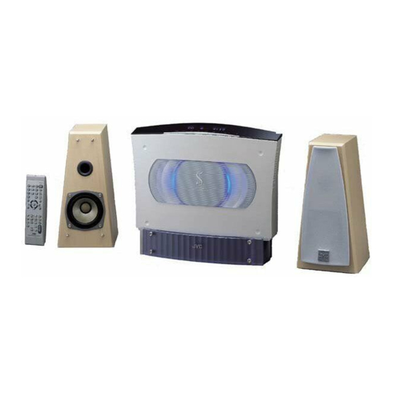
COMPACT COMPONENT SYSTEM
STANDBY/ON
1
2
3
PLAY MODE
4
5
6
REPEAT
7
8
9
FM MODE
10
+
10
BASS
TREBLE
SET
MD/AUX
CANCEL
FM/AM
DISPLAY
DIMMER
SLEEP
AHB PRO
CLOCK
OPEN/
/TIMER
CLOSE
VOLUME
SP-VSDT6
Contents
Safety precautions
Preventing static electricity
Important for laser products
Disassembly method
Flow of functional operation
until TOC read
VS-DT6
COMPACT COMPONENT SYSTEM
CA-VSDT6
1-2
1-3
1-4
1-5
1-15
COPYRIGHT
2002 VICTOR COMPANY OF JAPAN, LTD.
UP ---------------------------- Korea
SP-VSDT6
Error code
Maintenance of laser pickup
Replacement of laser pickup
Description of major ICs
VS-DT6
Area suffix
1-16
1-17
1-17
1-18
29
No.21104
May. 2002
Advertisement

Subscribe to Our Youtube Channel
Related Manuals for JVC VS-DT6


Summary of Contents for JVC VS-DT6
- Page 1 VS-DT6 SERVICE MANUAL COMPACT COMPONENT SYSTEM VS-DT6 Area suffix UP ---------------------------- Korea COMPACT COMPONENT SYSTEM STANDBY/ON PLAY MODE REPEAT FM MODE BASS TREBLE MD/AUX CANCEL FM/AM DISPLAY DIMMER SLEEP AHB PRO CLOCK OPEN/ /TIMER CLOSE VOLUME SP-VSDT6 CA-VSDT6 SP-VSDT6 Contents...
- Page 2 VS-DT6 1. This design of this product contains special hardware and many circuits and components specially for safety purposes. For continued protection, no changes should be made to the original design unless authorized in writing by the manufacturer. Replacement parts must be identical to those used in the original circuits. Services should be performed by qualified personnel only.
- Page 3 VS-DT6 Preventing static electricity 1. Grounding to prevent damage by static electricity Electrostatic discharge (ESD), which occurs when static electricity stored in the body, fabric, etc. is discharged, can destroy the laser diode in the traverse unit (optical pickup). Take care to prevent this when performing repairs.
- Page 4 VS-DT6 Important for laser products 5.CAUTION : If safety switches malfunction, the laser is able 1.CLASS 1 LASER PRODUCT to function. 2.DANGER : Invisible laser radiation when open and inter 6.CAUTION : Use of controls, adjustments or performance of lock failed or defeated. Avoid direct exposure to beam.
- Page 5 VS-DT6 Disassembly method <Main body section> Removing the bottom panel Top panel (See Figs. 1 and 2.) From the rear side of the main body, remove the three screws A attaching the bottom panel. From the bottom side of the main body, remove the two screws B attaching the bottom panel.
- Page 6 VS-DT6 Removing the CD mechanism assembly (See Fig. 4.) Remove the bottom panel. CD mechanism assembly Remove the top panel. From the top side of the main body, disengage the CN802 claw c of the CD mechanism assembly and then remove the push button.
- Page 7 VS-DT6 Removing the tuner board (See Figs. 7 and 8.) Notch Remove the bottom panel. CD mechanism Remove the top panel. assembly wire Remove the CD mechanism assembly. Speaker board Tie band CN101 Disconnect the card wire from connector CN111 on the main board.
- Page 8 VS-DT6 Removing the main board (See Figs. 9 and 10.) Remove the bottom panel. Main board Power transformer Remove the top panel. Remove the CD mechanism assembly. Wire clamp Remove the front panel assembly. Remove the tuner board. CN191 Remove the speaker board.
- Page 9 VS-DT6 Removing the power transformer (See Fig. 12.) Remove the bottom panel. Remove the top panel. Power transformer Main board Tie band Remove the CD mechanism assembly. Wire clamp Washers Disengage the wire clamp and tie band bundling the wires of the power transformer.
- Page 10 VS-DT6 <Front panel assembly section> Door motor assembly Remove the bottom panel. Switch board Remove the top panel. Remove the CD mechanism assembly. Remove the front panel assembly. Removing the switch board (See Fig. 14.) From the back side of the front panel assembly,...
- Page 11 VS-DT6 <CD mechanism assembly section> Claw a Removing the LED board (See Fig. 1.) LED board From the top side of the CD mechanism assembly, disengage the claw a of the top chassis attaching the LED board and then remove the LED board.
- Page 12 VS-DT6 Removing the traverse mechanism assembly (See Fig. 4.) Traverse mechanism CD servo board assembly bracket Remove the CD servo board. Remove the two screws C attaching the CD servo board bracket. Remove the two screws D attaching the traverse mechanism assembly.
- Page 13 VS-DT6 Attaching the pickup unit Section f (See Figs. 7 and 8.) [Reference] Refer to the explanation of "Removing the pickup unit" on the preceding page. Attach the P.S. spring and rack plate to the pickup unit. Groove g Insert the shaft into the pickup unit.
- Page 14 VS-DT6 Removing the CD switch board (See Fig.10.) CD mechanism assembly Clamper base assembly Remove the CD mechanism assembly. From the top side of the CD mechanism assembly, remove the screw K attaching the CD switch board. Lift the CD switch board slightly and then remove the wire from connector CN101 on the CD switch board.
- Page 15 VS-DT6 Flow of functional operation until TOC read Check Point Slider turns REST Power ON Play Key Confirm that the voltage at the pin3 SW ON. of CN611 is "H"\"L"\"H". Automatic tuning of TE offset Laser ON Detection of disc...
- Page 16 VS-DT6 Error code Error code indication Error code is indicated on the FL display. This unit is placed horizontally. SOURCE PRESET SOURCE PRESET C O M P A C T C O M P O N E N T S Y S T E M This unit is placed vertically.
- Page 17 VS-DT6 Replacement of laser pickup Maintenance of laser pickup (1) Cleaning the pick up lens Before you replace the pick up, please try to Turn off the power switch and, disconnect the clean the lens with a alcohol soaked cotton power cord from the ac outlet.
- Page 18 VS-DT6 Description of major ICs MN101C30AKJ1 (IC701) : System control microcomputer 1. Terminal layout 2. Pin function Pin No. Symbol Function THERM Temperature detection, ON/OFF control of FAN_SW signal(pin 57) KEY1 Key switch input of the main body KEY2 Key switch input of the main body...
- Page 19 VS-DT6 Pin No. Symbol Function Connect to ground Connect to ground Connect to ground CDRSI CD reset output (Connect to FMU-F1.) Connect to ground BLCTL Not connect PSAVE Power save mode ON/OFF signal, SAVE=H CD power supply ON/OFF, not use...
- Page 20 VS-DT6 MN662790RSC (IC651) : Digital servo & Digital signal prossesor 1. Terminal layout 2. Pin function Pin No. Symbol Function BCLK Bit clock output for SRDATA LRCK LR signal separation output SRDATA Serial data output DVDD1 Power supply for digital circuit...
- Page 21 VS-DT6 Pin No. Symbol Function PLLF2 Not use DSLBDA Not use WVEL Not use RF signal input IREF Referrence current input Bias pin for DSL DSLF Loop filter pin for DSL PLLF Loop filter pin for PLL VCOF Loop filter pin for VCO...
- Page 22 VS-DT6 UPD780024AGKB62 (IC251) : Unit microcomputer 1. Terminal layout 2. Pin function Pin No. Symbol Function P50/A8 Connect to ground P59/A9 Not use Synchronous/asynchronous output MRDY Ready signal input CDINDEX Not use CDEMP Not use CDTNO Not use CDCOPY Not use...
- Page 23 VS-DT6 Pin No. Symbol Function Connect to external crystal oscillator VSS1 Ground terminal FLAG Flag signal input BLKCK Sub code block clock signal input /RFDET RF signal amplitude detecting signal input EQx2 Equalizer select signal input EQx4 Equalizer select signal input...
- Page 24 VS-DT6 MN101C35DKB (IC811) : FL driver microcomputer 1. Terminal layout 2. Pin function Pin No. Symbol Function Not connect FLDATA FL driver communication data input/output FLCLK FL driver communication clock input Not connect FLCS FL driver communication chip select input...
- Page 25 VS-DT6 AN22000A (IC601) : RF & Servo amplifier 1. Terminal layout 2. Block diagram 3TOUT VDET /RFDET FEOUT TEOUT TEBPF OFTR OFTR 3TENV VDET COFTR SUBT SUBT CBDO FBAL TBAL C.AGC GCTRL RF IN NRFDET RF OUT RF_EQ 3. Pin function...
- Page 26 VS-DT6 LA1838 (IC1) : FM AM IF amplifier & Detector, FM MPX Decoder 1. Terminal layout & Block diagram DECODER ANIT-BIRDIE P-DET BUFF RF.AMP MUTE STEREO AM IF PILOT 384KHz COMP S-METER AM/FM S-CLRVE S-METER IF-BUFF TUNING STEREO DRIVE DRIVE FM IF 2.
- Page 27 VS-DT6 LA6575H (IC801) : Focus & Spindle & Feed & Tracking BTL driver 1. Terminal layout 2. Block diagram 28 27 26 25 24 23 22 21 20 19 18 17 16 15 Signal Input MUTE system power MUTE is as follows:...
- Page 28 VS-DT6 LC72136N (IC2) : PLL frequency synthesizer 1. Terminal layout 2. Block diagram XOUT Phase Reference Detector Driver Charge Pump LPFOUT LPFIN Swallow Counter 1/16,1/17 4bit Unlock ST/MONO FMOSC Detector AM/FM AMOSC IF REQ 12bit Programmable SDIN FM/AMIF Drivers Universal Data Shift Register &...
- Page 29 VS-DT6 LC75342M (IC501) : E. volume 1. Terminal layout 2. Block diagram RSELO RTRE RBASS1 RBASS2 ROUT DATA CLOCK VREF TEST ROUT LOUT RBASS2 LBASS2 TEST RBASS1 LBASS1 RTRE LTRE LVref CONTROL CIRCUIT RSELO LSELO LOGIC DATA CIRCUIT INTERFACE CLOCK...
- Page 30 VS-DT6 VICTOR COMPANY OF JAPAN, LIMITED AUDIO & COMMUNICATION BUSINESS DIVISION PERSONAL & MOBILE NETWORK BUSINESS UNIT. 10-1,1Chome,Ohwatari-machi,maebashi-city,371-8543,Japan No.21104 200205...
- Page 31 VS-DT6 SCHEMATIC DIAGRAMS COMPACT COMPONENET SYSTEM VS-DT6 CD-ROM No.SML200205 Area suffix UP ---------------------------- Korea COMPACT COMPONENT SYSTEM STANDBY/ON PLAY MODE REPEAT FM MODE BASS TREBLE MD/AUX CANCEL FM/AM DISPLAY DIMMER SLEEP AHB PRO CLOCK OPEN/ /TIMER CLOSE VOLUME SP-VSDT6 CA-VSDT6...
- Page 32 In regard with component parts appearing on the silk-screen printed side (parts side) of the PWB diagrams, the parts that are printed over with black such as the resistor ( diode ( ) and ICP ( ) or identified by the " " mark nearby are critical for safety. (This regulation does not correspond to J and C version.)
- Page 33 VS-DT6 Block diagram Main body section CD servo board Main board Front board IC601 IC812 RF & Servo Front Pickup amplifier REMOCON IC811 DI811 CD switch Loading motor board board driver display MICOM IC251 Unit MICOM IC701 LVA10324-A2 Loading System...
- Page 34 VS-DT6 VS-DT6 Standard schematic diagrams (To D-1 on page 2-4) (To G-3 and G-4 on page 2-6) System control section CN111 CN171 QGF1205C1-13 QGF1016C1-17 K7003 QQR1183-001Z C7201 0.01 C7210 Q7005 KRC102-X R7201 2.7K R7202 2.7K Q7006 KRA102S-X Q7008 DTA114TKA-X STBDIM...
- Page 35 VS-DT6 Power amplifier/Power supply section J3601 J3001 GP1FA550TZ R5305 S3601 QSW0454-001 2SD2114K/VW/-X 2SC2412K/R/-X 2SD2114K/VW/-X Q1101 Q1115 Q1102 R1116 R1111 2.2K R1118 R1112 QGA2501C1-05 QGA2501C1-04 3.3K CN102 CN101 C5104 R1108 10/16 C1109 0.0022 R1114 R1307 R1309 9.1K C5107 C1103 C1104 R1110...
- Page 36 VS-DT6 VS-DT6 Tuner section Front end diagram QAU0161-001 0.0039 0.0022 0.47/50 0.047/16 470P 0.047/16 1/50 22/16 3.9K 10/16 0.001 10/16 100/16 1000P 1SS133-T2 0.022 1SS133-T2 0.022 3.3K QAX0677-001Z LC72136N 1SS133-T2 LA1838 1SS133-T2 QNB0153-001 QAX0677-001Z 5.6K DTA114YKA-X 150P QQR0793-001 150P 150P 1/50 0.022/16...
- Page 37 VS-DT6 CD servo control section R601 220k TBAL R602 FBAL C604 0.022 CN671 C603 0.022 C607 C601 C602 SQCK R257 /SW3 GCTL KCMND /SW2 R259 MSTAT KCLK R263 IC251 R251 MCLK R262 R252 MDATA UPD780024AGKB62 R253 R254 /DMUTE STAT /RESET...
- Page 38 VS-DT6 VS-DT6 FL control section DI811 QLF0100-001 C805 0.01/50 C810 C803 C808 C811 C804 100P/50 4.7/50 0.01/50 100P/50 4.7/50 C802 C801 CN811 0.01 100/6.3 QGF1016F2-17W C814 100P/50 C813 100P/50 X811 R893 NAX0248-001X FLDATA R892 FLCLK R891 FLCS Q821 IC811 DTC114TKA-X C812 0.01/50...
- Page 39 VS-DT6 Printed circuit boards Main board (Speaker board) CN103 C5504 (LED board) R5502 LF311 CN101 LF321 CN102 D5504 LF551 C3602 D5503 D5501 C3601 S3601 C3105 J3601 J5503 C3205 IC802 J3001 C8011 J5301 J5303 J5302 C5304 J1901 CN802 C5309 (Tuner board)
- Page 40 VS-DT6 VS-DT6 Front board CD servo board Forward side Reverse side Forward side K656 R656 R677 R655 R864 R619 K657 R657 R862 C616 K658 R658 R861 C615 R863 C612 CN612 C607 R605 R604 R603 C605 C622 R602 R681 C291 R618...
- Page 41 < M E M O >...
- Page 42 VS-DT6 VICTOR COMPANY OF JAPAN, LIMITED AUDIO & COMUNICATION BUSINESS DIVISION PERSONAL & MOBILE NETWORK BUSINESS UNIT. 10-1,1chome,Ohwatari-machi,Maebashi-city,371-8543,Japan 200205(V) No.21104SCH...
- Page 43 VS-DT6 PARTS LIST [ VS-DT6 ] * All printed circuit boards and its assemblies are not available as service parts. Area suffix UP ---------------------------- Korea - Contents - Exploded view of general assembly and parts list (Block No.M1) 3- 3 3- 5 CD mechanism assembly and parts list (Block No.MB)
- Page 44 VS-DT6 < M E M O >...
- Page 45 VS-DT6 Exploded view of general assembly and parts list Block No. Power amplifier board Main board Tuner board 69 72 Switch board Speaker board 16.10 16.20 Open/Close board FL board...
- Page 46 VS-DT6 VS-DT6 Parts list (General assembly) Parts list (General assembly) Block No. M1MM Block No. M1MM Item Parts number Parts name Q'ty Description Area Item Parts number Parts name Q'ty Description Area GV10091-001A MOVING BASE GV40333-001A SPACER GV40269-001A ROLLER GV40330-001A...
- Page 47 VS-DT6 CD mechanism assembly and parts list Block No. FMU-F1-1M Grease = JVG-31N = JC-803B = JVS-1003 Back side CD switch A=0.6 0.2mm board SLIT WASHER 131.3 0.1mm Gap 'A' Gap 'A' 13.3 0.1mm 0 0.1mm 6.7 0.1mm Tra-mecha CD servo board...
- Page 48 VS-DT6 Parts list (CD mechanism) Block No. MBMM Item Parts number Parts name Q'ty Description Area LV10647-005A LOADING BASE LV33481-004A KICK LEVER UNIT LV42819-002A COMP.SPRING LV21204-003A SLIDE CAM LV42977-001A CAM SPRING LV33336-001A UD GEAR WJM0294-002A E-SI C WIRE C-F QJJ024-041504...
- Page 49 VS-DT6 Parts list (CD mechanism) Block No. MBMM Item Description Parts number Parts name Q'ty Area LV42965-001A ROD SPRING QUQ210-0705DF FFC WIRE CD PWB BKT LV33345-001A QYSBSF2006Z SCREW 4 FOR PWB/BKT QYSBSF2006Z SCREW 2 FOR PWB LV10650-003A T.CHASSIS LV33349-002A MIDDLE GEAR...
- Page 50 VS-DT6 Electrical parts list (Main board) Block No. 01 Item Parts number Parts name Remarks Area Item Parts number Parts name Remarks Area NCB31CK-223X C CAPACITOR CN 1 QGF1205C1-13 CONNECTOR NCB31CK-103X C CAPACITOR CN101 QGA2501C1-04 4P CONNECTOR FROM SPK.JACK QEKC1CM-106Z...
- Page 51 VS-DT6 Electrical parts list (Main board) Block No. 01 Item Parts number Parts name Remarks Area Item Parts number Parts name Remarks Area C1912 NCS31HJ-221X C CAPACITOR C5201 QEKC1HM-475Z E CAPACITOR 4.7MF 20% 50V C1913 NCB31HK-103X C CAPACITOR C5202 QEKC1HM-475Z E CAPACITOR 4.7MF 20% 50V...
- Page 52 VS-DT6 Electrical parts list (Main board) Block No. 01 Item Parts number Parts name Remarks Area Item Parts number Parts name Remarks Area D1905 MTZJ10A-T2 ZENER DIODE SW10 K5304 QQR1183-001Z FERRITE BEADS AUX OUT D1906 MTZJ11A-T2 ZENER DIODE R.FIL K7001...
- Page 53 VS-DT6 Electrical parts list (Main board) Block No. 01 Item Parts number Parts name Remarks Area Item Parts number Parts name Remarks Area Q3801 KTA1023/OY/-T TRANSISTOR R 41 NRSA63J-332X MG RESISTOR Q3802 KRC114M-T TRANSISTOR R 43 NRSA63J-392X MG RESISTOR Q3806...
- Page 54 VS-DT6 Electrical parts list (Main board) Block No. 01 Item Parts number Parts name Remarks Area Item Parts number Parts name Remarks Area R1906 NRSA63J-102X MG RESISTOR R3811 QRJ146J-2R2X UNF C RESISTOR 2.2 5% 1/4W R1907 QRE141J-102Y C RESISTOR 1.0K 5% 1/4W...
- Page 55 VS-DT6 Electrical parts list (Main board) Block No. 01 Item Parts number Parts name Remarks Area Item Parts number Parts name Remarks Area R7121 NRSA63J-222X MG RESISTOR QQR0793-001 R7122 NRSA63J-222X MG RESISTOR TH701 QAD0015-103Z THERMISTOR R7123 NRSA63J-222X MG RESISTOR TU 1...
- Page 56 VS-DT6 Electrical parts list (Front board) Block No. 02 Item Parts number Parts name Remarks Area Item Parts number Parts name Remarks Area C 801 NEA70JM-107X E CAPACITOR R 876 NRSA63J-122X MG RESISTOR C 802 NCB31HK-103X C CAPACITOR R 877...
- Page 57 VS-DT6 Electrical parts list (CD servo board) Block No. 03 Item Parts number Parts name Remarks Area Item Parts number Parts name Remarks Area C 254 QERF1AM-476Z E CAPACITOR 47MF 20% 10V IC601 AN22000A-W RF AMP C 255 NCB31CK-104X C CAPACITOR...
- Page 58 VS-DT6 Electrical parts list (CD servo board) Block No. 03 Item Parts number Parts name Remarks Area R 669 NRSA63J-562X MG RESISTOR R 671 NRSA63J-684X MG RESISTOR R 675 NRSA63J-100X MG RESISTOR R 681 NRSA63J-0R0X MG RESISTOR R 682 NRSA63J-102X...
- Page 59 VS-DT6 < M E M O > 3-17...
- Page 60 VS-DT6 Packing materials and accessories parts list Block No. Block No. A4~A7 A12, A15 A1 A3 3-18...
- Page 61 VS-DT6 Parts list (Packing) Block No. M3MM Item Description Parts number Parts name Q'ty Area GV30381-003A CARTON BOX GV10099-001A CUSHION(L) 1 (L) CUSHION(R) 1 (R) GV10099-002A GV30353-001A CARTON SPACER(A QPC04504515P POLY BAG 1 FOR SET QPA02503503P POLY BAG 1 FOR INST...
Need help?
Do you have a question about the VS-DT6 and is the answer not in the manual?
Questions and answers