MSA M1 Operating Manual
Entry control board
Hide thumbs
Also See for M1:
- Operating manual (37 pages) ,
- Cleaning and disinfection manual (27 pages) ,
- Quick start manual (2 pages)
Table of Contents
Advertisement
Advertisement
Table of Contents

Related Manuals for MSA M1


Summary of Contents for MSA M1
- Page 1 Operating Manual M1 Entry Control Board Order No.: 10212889/04 MSAsafety.com...
- Page 2 The Declaration of Conformity can be found under the following link: https://MSAsafety.com/DoC. MSA is a registered trademark of MSA Technology, LLC in the US, Europe and other Countries. For all other trademarks visit https://us.msasafety.com/Trademarks. This product incorporates Bluetooth® wireless technology. The Bluetooth word mark and logos are registered trademarks owned by Bluetooth SIG, Inc., and any use of such marks by MSA is under license.
-
Page 3: Table Of Contents
3.2.1 Setting up the ECB Clock 3.2.2 Setting Up the Tablet Clock via Designated Menu Items Pre-Setup: Connection to the Telemetry System 3.3.1 Connecting to a Network with a Single MSA HUB 3.3.2 Connecting to a Network with more MSA HUBs Turning On/Off... - Page 4 Manual Logoff Troubleshooting Sending Debug Logs to the Customer Service Disposal Maintenance Daily Checks Replacing the Clock Batteries Cleaning Software Update Marking/Certification Marking Certification Installing Accessories 10.1 Shoulder Strap 10.2 Tripod Adapter 10.3 Display Protection Pouch Technical Data Ordering Information 12.1 Spare Parts 12.2...
-
Page 5: Safety Regulations
Correct Use The M1 Entry Control Board (ECB), in this manual also referred to as device, is an electronic monitoring unit to control the respiratory status of individual breathing apparatus (BA) wearers. The ECB is part of a telemetry system: MSA's long range radio between the M1 Control Module of the BAs and MSA HUB as well as a local area network connection between the ECB and the MSA HUB are used to transfer the data and the recorded logs. - Page 6 1 Safety Regulations Product liability claims, warranties and guarantees made by MSA with respect to the device are voided, if it is not used, serviced or maintained in accordance with the instructions in this manual.
-
Page 7: Description
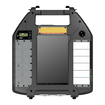
Status LEDs The Entry Control Board (ECB) is a monitoring tool to be used in combination with MSA HUB and M1 Control Module(s) to supervise the connected SCBA users. The device consists of a solid housing with an integrated tablet computer. The display shows the current operating data of the breathing apparatus (BA) connected via their M1 Control Module. -
Page 8: Digital Clock
2 Description The ECB is equipped with a battery-powered digital clock. The tablet computer is charged via the 2-Pin charging adapter. Status LEDs on the right top of the display indicate the power, battery and network connection status of the ECB. Green, yellow and red colour bars indicate the pressure state of the connected BAs and yellow and red background colours indicate warning and alarm notifications. -
Page 9: Tally
There are two tally colours available: yellow for BAs with one pressure cylinder and red for twin cylinder BAs. The tally is not included in the scope of delivery of the ECB since it is part of the MSA M1 SCBA with a Control Module. -
Page 10: Setting Up The Telemetry System
Setting Up the Telemetry System First of all, the MSA HUB needs to be configured through the A2 Software. The HUB provides a default network for the A2 Software to access. Default login data are to be found in the inside of the HUB housing. - Page 11 2 Description User selected display time: TTW, TOW ECP name or Elapsed time* Settings menu Empty tally slot bar Low battery status (appears when Current time battery breaches ≤25%) Information bar of BA wearer Evacuation button for all teams and operating data team members Team name/assignment...
- Page 12 2 Description WARNING! The time of whistle calculation is based on the ECB clock and may not correspond to the tablet clock. Use the ECB clock when comparing time of whistle to the current time. The actual time to whistle may be less than the time to whistle displayed. The actual time of whistle may be earlier than the time displayed.
-
Page 13: Before Use
WARNING! Risk of Explosion: Do not charge the ECB where an explosive atmosphere may be present. Use only the MSA provided charging cord. The batteries must be charged at an ambient temperature of 0 to +50°C. Failure to follow these warnings can result in serious personal injury or death. -
Page 14: Setting Up The Tablet Clock Via Designated Menu Items
Pre-Setup: Connection to the Telemetry System The Entry Control Board (ECB) has to pre-setup to connect to a MSA HUB infrastructure. Once this connection has been configured via WiFi, the ECB does not have to be reconfigured. It reconnects automatically to the provided network of the MSA HUB. -
Page 15: Connecting To A Network With A Single Msa Hub
3 Before Use 3.3.1 Connecting to a Network with a Single MSA HUB 1. Turn on the Entry Control Board. a. Press the power button for about 5 seconds. The tablet computer automatically starts the ECB app. The ECB is searching for a network. - Page 16 3 Before Use 3. Tap on the entry field Enter Password. A keyboard is displayed. 4. Enter the default password found on the HUB type label. The ECB is connecting to the HUB.
-
Page 17: Connecting To A Network With More Msa Hubs
ECB does not find a HUB. 3.3.2 Connecting to a Network with more MSA HUBs 1. Turn on the Entry Control Board. a. Press the power button for about 5 seconds. The tablet computer automatically starts the ECB app. - Page 18 3 Before Use The ECB is searching for a network. 2. Select the desired network. NOTE: The MSA HUB networks are for networks with a single HUB only. 3. Enter the network password. The ECB is connected to the network.
-
Page 19: Use
Set the ECB and tablet clock so they display the same time. See chapter3.2 for setting the clocks. Connecting the Entry Control Board to MSA HUB When already set up, the ECB automatically connects to the known network provided by the MSA HUB. - Page 20 Otherwise, see chapter 1. Turn on the Entry Control Board. a. Press the power button for about 5 seconds. The tablet computer automatically starts the ECB app. The ECB is searching for a network. 2. Select the desired MSA HUB network.
- Page 21 4 Use The ECB is connecting to the HUB. The ECB is connected to the HUB.
-
Page 22: Creating A New Entry Control Point
4 Use Creating a New Entry Control Point 1. Tap on the entry field Enter ECP name. A keyboard is displayed. 2. Enter a name for the new ECP following the local guidelines, e.g. Alpha. - Page 23 4 Use 3. Tap on Save. The new ECP is created.
-
Page 24: Connecting To An Entry Control Point
4 Use Connecting to an Entry Control Point 1. Open the dropdown menu of the existing ECPs. 2. Select the relevant ECP, e.g. Alpha. -
Page 25: Configuring Settings
4 Use 3. Tap on Save. The ECP is selected. Configuring Settings Tap on the menu symbol. The settings are displayed. To leave the Settings menu, tap on the information bars list. -
Page 26: Switching Into Dark Mode
4 Use 4.6.1 Switching into Dark Mode In the Settings menu, tap on the colour theme symbol. The dark mode is activated. -
Page 27: Changing The Time Display
4 Use 4.6.2 Changing the Time Display In the Settings menu, tap on the desired time selection, e.g. Elapsed Time. The time display is changed. To leave the Settings menu, tap on the information bars list. -
Page 28: Changing The Wifi Network
4 Use 4.6.3 Changing the WiFi Network 1. In the Settings menu, open the Connectivity section. 2. Tap on CHANGE WIFI. -
Page 29: App Information
4 Use 3. Select the new WiFi network from the list. The WiFi network is changed. 4.6.4 App Information Information about the app version, legal documents and licenses are found in this section. In the Settings menu, open the About section. The app information is displayed. -
Page 30: Contact Support
Entry Control Board (ECB) using the tally. The tally is attached to the safety key of the M1 Control Module. Therefore, every tally is assigned to a Control Module. When opening the compressed air cylinder, the Control Module connects to the MSA HUB and the current operating data of the breathing apparatus is transferred to the ECB. - Page 31 4 Use 4. Put the tally into the tally reader. The ECB is connecting to the M1 Control Module. If the connection fails, refer to chapter The first bar on the display allows to create a new team. 5. Tap on NEW TEAM.
- Page 32 4 Use A window pops up. 6. Enter a team name, e.g. “1”. NOTE: Only numbers from 1 to 99 can be entered. The BA wearer is assigned to the team. When the BA wearer opens the pressure cylinder, the first bar on the ECB display changes into a display of the current operating data: The cylinder pressure that is automatically transmitted via long range radio after successful login...
-
Page 33: Logging On Additional Ba Wearers
4 Use Logging On Additional BA Wearers The ECB allows the creation of 6 individual teams, but it is recommended to have at least 2 members in one team. 4.8.1 Assigning to an Existing Team 1. Open the compressed air cylinder of the BA wearer. 2. -
Page 34: Assigning To A New Team
4 Use 7. If needed, write further information on the inscription field. 8. Repeat for any further tally. NOTE: If more than 6 BA wearers are entering the incident scene from the same ECP, set up another ECB. 4.8.2 Assigning to a New Team 1. -
Page 35: Adding Ba Wearers Manually
4 Use WARNING! Tallies must be placed into tally slots from top to bottom in the same order in which they are scanned into the tally reader. Placing tallies into the tally slots out of order will result in a mismatch between the tallies and the BA data shown on the ECB. -
Page 36: Using Repeaters
It is recommended to place the device on the ground and pull up the goose neck to elevate the antenna 60 cm from any surface. In order to take advantage of the full capability of the system connect M1 Control Modules directly to the MSA HUB. -
Page 37: 4.10.1 Initiating A Single Team Evacuation
4 Use Evacuation Statuses Symbol Description The evacuation button can only be pressed by the ECO. After that, an evacuation request is sent to the affected BA wearers in the risk area. The evacuation request is sent out, but has not reached the Control Module of the affected BA wearers yet. - Page 38 4 Use 2. In the pop up window, tap on the EVACUATE button. The evacuation request is sent to the Control Modules of the affected BA wearers. When the Control Module receives the evacuation request, an acoustic alarm is triggered. The status on the ECB then changes from “sent” to “received”.
- Page 39 4 Use When the BA wearer has noticed the evacuation request, the notification has to be confirmed. The risk area must be left to get back to the ECP. When a BA wearer has confirmed the evacuation request, that status on the ECB changes from "received"...
-
Page 40: 4.10.2 Initiating A Collective Evacuation
4 Use 4.10.2 Initiating a Collective Evacuation 1. Tap on the EVACUATE ALL button. 2. In the pop up window, tap on the EVACUATE button. - Page 41 4 Use The evacuation request is sent to the Control Modules of all BA wearers. When the Control Modules receive the evacuation request, an acoustic alarm is triggered. The status on the ECB then changes from “sent” to “received”. When the BA wearers have noticed the evacuation request, it has to be confirmed.
-
Page 42: 4.10.3 Incident States
ECB, refer to chapter 4.10.3 Incident States During operation the user can set incident state points: Incident Reached On Withdrawal The M1 Control Module calculates a withdrawal pressure level based on the use of pressure to reach the incident scene. - Page 43 M1 Control Module (see M1 Control Module Operating Manual). The BA wearer is on retreat. If a user does not set withdrawal state prior to withdrawal alarm the M1 Control Module shows withdrawal alarm and the Entry Control Board changes to active...
-
Page 44: Alarms/Warnings
4 Use Once the user has confirmed the withdrawal alarm the display changes to “Withdrawal Confirmed”. 4.11 Alarms/Warnings The following table describes all alarms that can show up on the Entry Control Board. Notification Display Description Actions to Acknowledge the Alarm on the ECB Radio The radio connection... - Page 45 4 Use Notification Display Description Actions to Acknowledge the Alarm on the ECB Low battery The battery status of the Confirm the notification. alarm BA wearer’s Control The alarm will still be visible in the Module is below a related bar: remaining operating time of 2 hours.
- Page 46 4 Use Notification Display Description Actions to Acknowledge the Alarm on the ECB Motion alarm The man down alarm is Confirm the notification. triggered automatically The alarm will still be visible in the from the Control Module related bar: using the integrated motion detection sensor based on the predefined thresholds in the control module.
- Page 47 Low battery appears when Connect ECB to battery charger. (ECB) battery breaches ≤25% and shows the battery drain from then on. Chemical When M1 Control Module Protection has been prepared with a Suite (CPS) special tag (CPS Mode) Mode and started Slot shows...
-
Page 48: After Use
5 After Use After Use At the Entry Control Point, all BA wearers logged on must be logged off by being identified by the Entry Control Officer (ECO) who removes the related tally from the Entry Control Board. Logging Off a BA Wearer 1. -
Page 49: Troubleshooting
Display Description Action of the Entry Control Operative Connection When trying to connect the ECB Restart the MSA HUB. If the between ECB to a HUB, no available HUB can condition persists, tap on and HUB fails be found. CHANGE WIFI to search for the correct network. - Page 50 6 Troubleshooting a. Tap on the and symbol of the tablet computer simultaneously. 2. Connect the ECB to the internet. 3. Use or install an email client in the ECB tablet, e.g. gmail. 4. Compose a new message and attach the log file. a.
- Page 51 6 Troubleshooting b. Open the Documents folder. c. Open the ECB-Logs folder.
- Page 52 6 Troubleshooting d. Choose the most recent date file the date with the .csv file format you want to send, e.g. the file from March 23, 2020. 5. Send the file to the customer service (ecb-email@safetyio-help.com).
-
Page 53: Disposal
7 Disposal Disposal For disposal of the device and batteries, observe the local regulations. -
Page 54: Maintenance
Maintenance WARNING! Do not attempt to repair the ECB. Repair of the ECB must be performed by a person authorized by MSA. Failure to follow this warning can result in serious personal injury or death. Repairs must only be carried out by the manufacturer or by a repair service authorized by the manufacturer. -
Page 55: Cleaning
8 Maintenance Cleaning NOTICE Do not use alcoholic detergents to clean the ECB. Otherwise, the device or any parts of the device may be damaged. Periodically clean the device with a damp cloth and soapy water. Only for cleaning the whiteboard inscription fields and the tally, use petroleum ether. Software Update In case there is a new update for the Entry Control Board app available, the following notification will be visible in the app:... - Page 56 1. Leave the ECB app. a. Tap on the v and o symbol of the tablet computer simultaneously. 2. On the main screen, open the Google Play Store app. 3. Search for "Entry Control Board". 4. Select the M1 Entry Control Board app.
- Page 57 8 Maintenance 5. Open the app. 6. Tap on Update. The app will be updated.
-
Page 58: Marking/Certification
9 Marking/Certification Marking/Certification Marking Figure 1 ECB markings label Company logo Date of manufacture (YYYY) Serial-No. Certification The Declaration of Conformity can be found under the following link: https://MSAsafety.com/DoC... -
Page 59: Installing Accessories
10 Installing Accessories Installing Accessories 10.1 Shoulder Strap The shoulder strap is part of the scope of delivery. To install the shoulder strap: 1. Place both ends of the strap at the shoulder strap attachment slits. a. Make sure the strap is not twisted. b. -
Page 60: Tripod Adapter
10 Installing Accessories To remove the shoulder strap: 1. Rotate the metal ring between the connection strap and the shoulder strap. 2. When reaching the end of the metal ring, pull out the loop of the connection strap. 3. Repeat for the other end of the shoulder strap. The Shoulder strap is removed from the ECB. -
Page 61: Display Protection Pouch
There are pockets to store objects like a pad of paper, a high-visibility vest and pens. On the back of the pouch is a vision panel where a table for calculating the working duration can be stored, in case the working duration needs to be calculated without using the ECB. The table can be downloaded on the MSA website at https://MSAsafety.com. - Page 62 10 Installing Accessories Figure 3 ECB pouch To attach as a protection pouch: 1. Lay the pouch over the ECB front. 2. Attach the two snaps to the relating counterparts on the ECB handle. 3. At the bottom of the pouch, put the two elastic straps over the supporting feet of the ECB housing.
- Page 63 10 Installing Accessories To turn into rain or sun protection: Push the narrow side of the pouch into the two hooks on the carrying handle. The pouch is fixed as sun or rain protection. When not in use, the pouch can be removed or turned behind the ECB.
-
Page 64: Technical Data
11 Technical Data Technical Data Dimensions L x W x H (housing) 510 mm x 440 mm x 65 mm Weight 4200 g Ambient temperature range -18 °C to +58 °C Storage temperature range -18 °C to +58 °C Humidity 10 to 90 % r.H. -
Page 65: Ordering Information
Cleaning Cloth, ECB (5 pcs) 10212470-SP Tally compl., ECB, yellow (10 pcs) 10212472-SP Tally compl., ECB, red (10 pcs) 10212473-SP 12.2 Accessories Description Part Number Tripod adapter, compl., ECB 10213720 Truck charger, set, ECB 10213719 M1 ECB, Complete Charging Set 10213741... - Page 66 For local MSA contacts, please visit us at MSAsafety.com...
Need help?
Do you have a question about the M1 and is the answer not in the manual?
Questions and answers
How to show percentage of battery on toolbar
The MSA M1 manual does not provide specific instructions on how to display the battery percentage on the toolbar. However, it mentions that the LEDs indicate battery life and that the battery state of charge can be accessed in the Service Mode menu. To check the battery state of charge, you may need to enter Service Mode by pressing one of the green buttons for more than 5 seconds and navigating through the menu options.
This answer is automatically generated