
Subscribe to Our Youtube Channel
Related Manuals for Nibe RCU 10


Summary of Contents for Nibe RCU 10
- Page 1 INSTALLATION AND MAINTENANCE INSTRUCTIONS RCU 10 MOS GB 0546-1 511401 FOR FIGHTER 360P/1130/1230/1320 RCU 10...
-
Page 3: Table Of Contents
GSM modem ............6 Digital inputs ............6 SMS commands ..........19 Indicators Web interface – FIGHTER 1130/1230 Indicators on RCU 10 .......... 7 Overview page ............ 20 Indicator on GSM modem ........7 Operating data ............ 21 Operating data, extended ........22 Starting Operating data, external units ...... -
Page 4: General
General In order to get the ultimate benefit from your RCU 10 communications unit you should read through these Installation and Maintenance Instructions. To be completed when the communications unit has been installed Installation date Installation engineers MAC ID Date __________... -
Page 5: Product Description
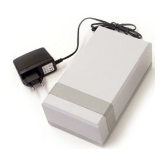
Product description The RCU 10 consists of a communications module, a It is possible to connect to the RCU 10 two indepen- GSM modem with an antenna and a separate power dent switch functions to detect external events such as supply unit with jack for plugging into a wall socket. -
Page 6: Installation Assembly
Open the plastic cover by separating its two halves. pump modular connector that is on the CPU card (34). The RCU 10 is placed outside the heat pump and its For communication to work, the CPU card in the best location is mounted on a wall. -
Page 7: Network Connections
A network with the RCU 10 connected to a router or hub/switch is recommended. For connection direct to a computer with Internet connection, two network... -
Page 8: Gsm Modem
2 VDC for an inactive signal. Antenna Terminal number Function The RCU 10 is delivered with an antenna, that is ini- tially kept rolled up inside the outer casing. If reception Voltage feed (12 VDC) at the installation site is poor, try moving the antenna... -
Page 9: Indicators
Indicators Indicators on RCU 10 Not lit The RCU has no voltage Steady green RCU 10 in operation Steady orange On starting Not lit Waiting Flashing green TX serial channel Flashing red RX serial channel Steady orange On starting Not lit... -
Page 10: Starting General
When the program starts, it will automatically search parameters in the RCU 10. The program can search for an RCU 10 network connection. A list will be dis- for RCU 10 units on an Ethernet network, after which played of all units that are found. A new search can be the IP address, network mask, gateway, DNS, etc. - Page 11 Host name: Host name for RCU 10 (any) characters. The preset password is ”admin”. On pressing the “Set” button the RCU 10 will restart, NOTE! after which the new settings will be activated. Only A-Z, a-z and 0-9 are permitted to...
-
Page 12: Logging In
Starting Logging in Start the browser (such as Internet Explorer) and enter the selected IP address in the RCU 10. If the IP address is chosen for example to be 10.2.15.21, then ”http://10.2.15.21” is entered into the browser address field, followed by pressing the Enter button. -
Page 13: Web Interface
The actual displayed images may differ somewhat, depending on the currently installed configuration. The RCU 10 has two menus, a top menu and a side menu. The top menu provides navigation to different areas of the NIBE web site (requires Internet connec- tion) and resetting of the RCU 10 to another language (requires administrative or writing authority). -
Page 14: Web Interface - Settings
The logging interval defines at which intervals the logged values shall be saved. Selectable intervals are To change the language used in the RCU 10, click on every 10 seconds, 30 seconds, 1, 2, 5, 10, 30 and the flag for the desired language in the top menu, or 60 minutes. -
Page 15: Module
The informationen in the “Building” display is then used when the RCU 10 sends an alarm via E- mail or as a text message. The RCU 10 can be restarted remotely by clicking on “Restart”. -
Page 16: Modem
Here all the settings that affect the GSM modem can Here takes place handling of users who shall have the be made. right to log in to the RCU 10. Click on “Add” to add a new user. Existing user information can be edited by clicking on the names. -
Page 17: Web Interface - Fighter 360P
D Temperature, hot water sensor Menu 1.0* E Evaporation temperature Menu 5.0* Extract air temperature Menu 5.1* G Exhaust air temperature Menu 5.2* H Outside temperature Menu 4.0* Operating indications Lit lamp indicates an active function. Equivalent menu number in FIGHTER 360P RCU 10... -
Page 18: Operating Data
FIGHTER 360P’s component list is shown. To change a value, click on ”arrow down” and select a value from the scrolling list, confirm with ”Set”. After a few seconds the change is confirmed by FIGHTER 360P and the relevant value is updated. RCU 10... -
Page 19: Operating Data, Extended
In this form the heat regulation parameters can be The change in value presumes that the user has changed by clicking on ”arrow down” and selecting a logged in with writing or administration authority. value from the scrolling list, confirming thereafter with ”Set”. RCU 10... -
Page 20: Alarm/Status
Web interface – FIGHTER 360P Alarm/status This form shows the common alarms that the heat Here the log files that are in the RCU 10 can be pump has indicated. fetched. The parameter log contains selected logged values (see the “Web interface – Settings” > “Log”...
Need help?
Do you have a question about the RCU 10 and is the answer not in the manual?
Questions and answers