Nibe VVM 325 Installer Manual
Indoor module
Hide thumbs
Also See for VVM 325:
- Installer manual (144 pages) ,
- Installer manual (40 pages) ,
- Installer manual (68 pages)
Table of Contents
Advertisement
Quick Links
Advertisement
Table of Contents

Related Manuals for Nibe VVM 325


Summary of Contents for Nibe VVM 325
- Page 1 Installer manual NIBE™ VVM 325 Indoor module IHB GB 1524-2 331115...
- Page 2 Quick guide Navigation Ok button (confirm/select) Back button (back/undo/exit) Control knob (move/increase/reduce) A detailed explanation of the button functions can be found on page 34. How to scroll through menus and make different settings is described on page 35. Set the indoor climate INDOOR CLIMATE HOT WATER MY INSTALLATION...
-
Page 3: Table Of Contents
11 Accessories Settings Optional connections 12 Technical data Connecting accessories Dimensions and setting-out coordinates 6 Commissioning and adjusting Technical specifications Preparations Electrical circuit diagram, 3 x 400V Filling and venting Index Start-up and inspection NIBE™ VVM 325 Table of Contents |... -
Page 4: Important Information
Marking VVM 325 is CE marked and fulfils IP21. The CE marking means that NIBE ensures that the product meets all regulations that are placed on it based on relevant EU directives. The CE mark is obligat- ory for most products sold in the EU, regardless where they are made. - Page 5 Safety valve Electricity (page 19) Connected communication Circuit fuses Fuses, indoor module Fuses property Outside sensor Room sensor Current sensor Safety breaker Earth circuit-breaker Setting of emergency mode thermostat Miscellaneous Docked to NIBE™ VVM 325 Chapter 1 | Important information...
- Page 6 NIBE Energy Systems France Sarl, Zone industrielle RD 28, Rue du Pou du Ciel, 01600 Reyrieux Tel : 04 74 00 92 92 Fax : 04 74 00 42 00 E-mail: info@nibe.fr www.nibe.fr NIBE Energy Systems Ltd, 3C Broom Business Park, Bridge Way, Chesterfield S41 9QG Tel: 0845 095 1200 Fax: 0845 095 1201 E-mail: info@nibe.co.uk www.nibe.co.uk...
-
Page 7: Delivery And Handling
2 Delivery and handling Transport Supplied components 40 mm VVM 325 should be transported and stored vertically in a dry place. However, the VVM 325 may be carefully laid on its back when being moved into a building. Assembly Outside sensor Room sensor Position VVM 325 on a firm base that can take the ■... -
Page 8: Removing The Covers
1. Remove the screws from the upper and lower edges. 2. Twist the cover slightly outward. 3. Move the hatch backwards and slightly to the side. 4. Pull the cover to one side. 5. Pull the hatch forwards. Chapter 2 | Delivery and handling NIBE™ VVM 325... -
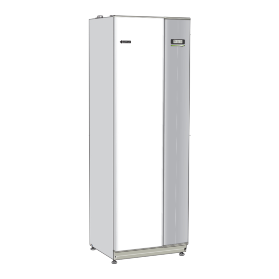
Page 9: Indoor Module's Design
3 Indoor module's design VVM 325 W130 QN10 BT63 VVM325 VVM325 AA4-XJ3 AA4-XJ4 FD1-SF2 FD1-BT30 AA1-S2 QM11 QM20 QM22 NIBE™ VVM 325 Chapter 3 | Indoor module's design... - Page 10 Miniature circuit-breaker Temperature limiter FD1- Resetting temperature limiter Main switch Rear side W130 Network cable for NIBE Uplink Pipe connections Miscellaneous Connection, heating medium supply line Ø22 Rating plate Serial number plate Connection, heating medium return line Ø22 Cable gland Cable gland Connection, cold water Ø22 mm...
-
Page 11: Pipe Connections
4 Pipe connections System diagram General pipe connections VVM 325 consists of water heater with charge coil, ex- Pipe installation must be carried out in accordance with pansion vessel, safety valve, filler valve, immersion current norms and directives. heater, circulation pumps, buffer vessel and control system. -
Page 12: Dimensions And Pipe Connections
Dimensions and pipe connec- tions Pipe dimensions Connection Heating medium supply line Ø Heating medium return line Ø Cold water Ø Hot water Ø Docking, in heating medium Ø Docking, out heating medium Ø Chapter 4 | Pipe connections NIBE™ VVM 325... - Page 13 XL1 Heating medium supply line Ø XL2 Heating medium return line Ø XL3 Cold water Ø XL4 Hot water Ø XL8 Docking, in heating medium Ø XL9 Docking, out heating medi- um Ø NIBE™ VVM 325 Chapter 4 | Pipe connections...
-
Page 14: Installation Alternative
F2040-8 all versions F2040-12 all versions VVM 325 can be connected to extra water heater, see below. Further option information is available at www.nibe.eu and in the respective assembly instructions for the ac- cessories used. See page 69 for a list of the accessories that can be used with VVM 325. - Page 15 Circulation pump, cooling QN12 Three way valve cooling/heating EB101 Heat pump FL10 Safety valve Miscel- Particle filter laneous Tapping valve EMK 300 QM40 Shut-off valve External electrical additional heat QM41 Shut-off valve Particle filter NIBE™ VVM 325 Chapter 4 | Pipe connections...
- Page 16 Outline diagram -CL11 -EP5 -BT51 -HQ4 -GP9 POOL -AA25 -EB15 -CL11-GP12 -CL11-QN19 -EP21 -EB101 -AA25 -BT2 -GP20 -QM41 -BT3 -QN25 -XL1 -QM40 -HQ1 -XL2 -FL10 -QM1 -XL8 -XL9 -XL2 -XL1 -XL3 -XL4 Chapter 4 | Pipe connections NIBE™ VVM 325...
- Page 17 60 °C. If the factory setting is changed, national regulations VVM 325 is equipped with shut off valves to facilitate must be observed. The setting is made in menu 5.1.1 any future servicing.
- Page 18 For connection of active cooling, ACS 310, see "Accessor- ies" on page 69. -EQ1 -EB15 -AA25 -GP13 -CP10 -GP12 -BT64 -QN12 -XL2 -XL1 -XL3 -XL4 -EB101 -QM41 -XL1 -QM40 -HQ1 -XL2 -FL10 -XL8 -QM1 -XL9 Chapter 4 | Pipe connections NIBE™ VVM 325...
- Page 19 Where there is a pool, F135 must be connected between pool and outdoor air heat pump. -CL11 -EP5 -AZ10 -BT51 -HQ4 -GP9 POOL -AA25 -EB15 -CL11 -GP12 -CL11 -QN19 -HQ1 -EB101 -QM41 -XL1 -QM40 -HQ1 -XL2 -FL10 -XL8 -QM1 -XL9 NIBE™ VVM 325 Chapter 4 | Pipe connections...
- Page 20 -CL11 -EP5 -AZ10 -BT51 -HQ4 -GP9 POOL -AA25 -EQ1 -EB15 -AA25 -GP13 -CL11 -GP12 -CP10 -GP12 -CL11 -QN19 -BT64 -QN12 -HQ1 -EB101 -QM41 -XL1 -QM40 -HQ1 -XL2 -FL10 -XL8 -QM1 -XL9 Chapter 4 | Pipe connections NIBE™ VVM 325...
-
Page 21: Electrical Connections
If the building is equipped with an earth-fault ■ force. VVM320 breaker, VVM 325 should be equipped with a separ- ate one. For the indoor module wiring diagram, see page 73. ■ Communication and sensor cables to external con- ■... - Page 22 1. Push the catch down. 1. Insert the screwdriver (A) and pry the catch care- fully downwards (B). 2. Angle out the cover and remove it. 2. Angle out the cover and remove it. Chapter 5 | Electrical connections NIBE™ VVM 325...
- Page 23 Cable lock Use a suitable tool to release/lock cables in the indoor module terminal blocks. NIBE™ VVM 325 Chapter 5 | Electrical connections...
-
Page 24: Connections
AA1:X2 must be moved toAA1:X9 (as illustrated). When connecting external operating voltage for the VVM 325 must be installed via an isolator switch with control system with separate earth-fault breaker, dis- a minimum breaking gap of 3 mm. Minimum cable... - Page 25 Room sensor Install the outdoor temperature sensor (BT1) in the VVM 325 is delivered with a room sensor supplied shade on a wall facing north or north-west, so it is un- (BT50). The room temperature sensor has up to three affected by the morning sun for example.
- Page 26 Communication If VVM 325 is to be connected to the heat pump, it is connected to terminals X4:13, X4:14 and X4:15 on the input card (AA3). F20XX VVM500 F2030/F2040 VVM 325 VVM325 VVM325 AA3-X4 AA3-X4 Chapter 5 | Electrical connections...
-
Page 27: Settings
The table displays the maximum phase current for the relevant electrical step for the indoor module. The tables display the maximum phase current for the relevant electrical step for the indoor module. NIBE™ VVM 325 Chapter 5 | Electrical connections... - Page 28 Power emergency mode, 3x400V (maximum elec- Output locking trical power, switched to 7 kW) VVM 325 follows applicable building regulations (BBR). För frånluftsvärme! This means that the maximum power output (maxim- um installed electrical output for heating) can be locked in menu 5.1.13.
-
Page 29: Optional Connections
If an external switch function or sensor is con- property at the same time as the electric addition is nected to VVM 325, the function to use input operating, there is a risk of the property's main fuse tripping. The electric boiler has integrated load monit- or output must be selected in menu 5.4, see... - Page 30 (effect on the system can be adjusted to the selected input (menu 5.4, see page 61) on ter- in the menu 4.1.5). minal block X6 on the input circuit board (AA3). Overcapacity mode (A: Closed, B: Closed) ■ Chapter 5 | Electrical connections NIBE™ VVM 325...
- Page 31 NOTE In systems with both underfloor heating and 1 2 3 radiators, NIBE ECS 40/41 should be used for C NO NC optimum operation. AA3-X7 VVM325 VVM325 Possible selection for AUX output (potential...
-
Page 32: Connecting Accessories
Connecting accessories Instructions for connecting accessories are provided in the manual accompanying the accessory. See page 69 for the list of the accessories that can be used with VVM 325. Chapter 5 | Electrical connections NIBE™ VVM 325... -
Page 33: Commissioning And Adjusting
Filling the climate system 1. Open the venting valve (QM20). 2. Open the filler valve (QM11). Fill VVM 325 with water. 3. When the water that exits the vent valve (QM20) is not mixed with air, close the vent valve. -
Page 34: Start-Up And Inspection
2. Press the OK button to skip between the pages in the start guide. During the start up guide the reversing valves and the shunt are run back and forth to help vent VVM 325 Name and menu number Caution... -
Page 35: Nibe™ Vvm
Select operating mode auto or manual when the indoor module is to run with the heat pump. Pump speed One of the circulation pumps (GP1) in VVM 325 is fre- quency controlled and adjusts itself using control and external heating requirement. Pressure Available pressure, circulation pump, GP1 Tillgängligt tryck cirkulationspump, GP12... -
Page 36: Control - Introduction
The control knob can be turned to the right or left. You can: ■ scroll in menus and between options. ■ increase and decrease the values. ■ change page in multiple page instructions (for example help text and service info). Chapter 7 | Control - Introduction NIBE™ VVM 325... -
Page 37: Menu System
HOT WATER Hot water temp. These two symbols indicate whether the compressor in the outdoor unit or addi- tional heat is blocked in VVM 325. These can, for example, be blocked de- Information about operation pending on which operating mode is se- lected in menu 4.2, if blocking is sched-... - Page 38 (at the page number) has been marked. 2. Press the OK button to skip between the steps in the start guide. If the start guide is left on this page it closes automatically in 60 min Chapter 7 | Control - Introduction NIBE™ VVM 325...
- Page 39 1. Use the control knob to select the help symbol. 2. Press the OK button. The help text often consists of several windows that you can scroll between using the control knob. NIBE™ VVM 325 Chapter 7 | Control - Introduction...
-
Page 40: Control - Menus
If the house has several climate systems, this is indicated on the display by a thermometer for each system. In Menu 1.1 choose between heating or cooling and then set the desired temperature in the next menu "temperature heating/cooling". Chapter 8 | Control - Menus NIBE™ VVM 325... - Page 41 1.1 during scheduling is set here. If the rooms sensor is installed the desired room tem- If necessary, the different return times can be changed perature is set in °C. in menu 1.9.6. NIBE™ VVM 325 Chapter 8 | Control - Menus...
- Page 42 Menu 1.3.3 - ventilation (accessory required) Increases or decreases in the ventilation to the accom- modation can be scheduled here for up to two time periods per day. Chapter 8 | Control - Menus NIBE™ VVM 325...
- Page 43 This menu has several sub-menus. curve Setting the curve slope for heating and cooling. external adjustment Setting the heat curve offset when the external contact is connected. NIBE™ VVM 325 Chapter 8 | Control - Menus...
- Page 44 If you only have one climate system, the num- ber of the curve is already marked when the menu window opens. 1. Select the climate system (if more than one) for which the curve is to be changed. Chapter 8 | Control - Menus NIBE™ VVM 325...
- Page 45 If a room sensor is installed and activated the desired room temperature (°C) is set. If there is more than one climate system the setting can be made separately for each system. NIBE™ VVM 325 Chapter 8 | Control - Menus...
- Page 46 (the difference between the desired and actual room temperature) in the room is to affect the supply tem- You can use VVM 325 to cool the house during hot perature to the climate system. A higher value gives a periods of the year.
- Page 47 When the room sensor for cooling/heating (BT74) is installed and activated in VVM 325, Here you can set how long VVM 325 is to wait before it returns to heating mode when the cooling demand you can select another sensor for control of has ceased or vice versa.
- Page 48 +Adjust is to have on calculated supply temperature. The higher the value, the greater the effect. *Support for +Adjust required NOTE +Adjust must first be selected in menu 5.4 ”soft inputs/outputs”. Chapter 8 | Control - Menus NIBE™ VVM 325...
-
Page 49: Menu 2 - Hot Water
The remaining time for the selected setting is shown to the right. Time period Adjusting When the time has run out VVM 325 returns to the mode set in menu 2.2. Schedule: The schedule to be changed is selected here. Select “off" to switch off... - Page 50 During the set periods the hot water cir- culation pump will run according to the settings above. "operating time" decide how long the hot water circu- lation pump must run per operating instance. Chapter 8 | Control - Menus NIBE™ VVM 325...
-
Page 51: Menu 3 - Info
Information about the additional heat's settings, oper- ating status and statistics can be obtained here. No changes can be made. The information is on several pages. Turn the control knob to scroll between the pages. NIBE™ VVM 325 Chapter 8 | Control - Menus... -
Page 52: Menu 4 - My System
Settings of indoor module work mode. Menu 4.1.3 - internet Menu 4.1 - plus functions Here you make settings for connecting VVM 325 to the Settings for any additional functions installed in VVM internet. 325 can be made in the sub menus. - Page 53 All settings made since opening the menu can be reset by marking "reset" and pressing the A connected user has a user account in NIBE Uplink™ OK button. which have been given permission to control and/or monitor your installation.
- Page 54 "SG electricity contracts. The function is based on hourly Ready". rates for the next 24 hours being retrieved via NIBE With low price mode of "SG Ready" and cooling oper- Uplink™ and therefore an internet connection and an ation the indoor temperature is not affected.
- Page 55 VVM 325 is closed. You can select up to 3 icons. the advanced user. This menu has several sub-menus. If you select more, the ones you selected first will disap- pear.
- Page 56 "stop heating" cannot be set door module. higher than "start cooling" if there is not a cooling/heating sensor. Chapter 8 | Control - Menus NIBE™ VVM 325...
- Page 57 Caution Caution Long term blocking can cause reduced comfort Long term scheduling of "quiet mode" can and operating economy. cause reduced comfort and operating eco- nomy. NIBE™ VVM 325 Chapter 8 | Control - Menus...
-
Page 58: Menu 5 - Service
) to default values. on the display to the right of the menus. forced control Forced control of the different compon- operating settings Operating settings for the indoor ents in the indoor module. module. Chapter 8 | Control - Menus NIBE™ VVM 325... - Page 59 Factory setting speed 1: 0 % system 1. Factory setting speed 2: 30 % Factory setting speed 3: 80 % Factory setting speed 4: 100 % NIBE™ VVM 325 Chapter 8 | Control - Menus...
- Page 60 Here you set the max. electrical output of the internal Use of this menu for other reasons may result electrical addition in VVM 325 and the fuse size for the in your installation not functioning as inten- installation.
- Page 61 Setting range: on/off Factory setting: off mixing valve amplifier Setting range: 0.1 –10.0 Default value: 1.0 mixing valve step delay Setting range: 10 – 300 s Default values: 30 s NIBE™ VVM 325 Chapter 8 | Control - Menus...
- Page 62 If the external addition is step controlled you can select when the addition is to start, set the maximum number Setting range: on/off of permitted steps and whether binary stepping is to Factory setting: off be used. Chapter 8 | Control - Menus NIBE™ VVM 325...
- Page 63 See page 32 for more information about the start guide. If operating mode "add. heat only" is to be See page 32 for more information about the start guide. used, select it in menu 4.2. NIBE™ VVM 325 Chapter 8 | Control - Menus...
- Page 64 Set the operating mode of the heating medium pump here. auto: The heating medium pump runs according to the current operating mode for VVM 325. intermittent: The heating medium pump starts and stops 20 seconds before and after the compressor in the heat pump.
-
Page 65: Service
NOTE Servicing should only be carried out by persons with the necessary expertise. VVM325 When replacing components on VVM 325 only replacement parts from NIBE may be used. Emergency mode Emergency mode is used in event of operational inter- ference and in conjunction with service. Hot water ca- FD1-SF2 pacity is reduced in this mode. - Page 66 10.00 2.245 8.045 2.083 6.514 1.916 VVM 325 is equipped with a USB socket in the display unit. This USB socket can be used to connect a USB 5.306 1.752 memory to update the software, save logged informa- 4.348 1.587 tion and handle the settings in VVM 325.
- Page 67 VVM 325 restarts. Set whether the present measurement values from NOTE VVM 325 are to be saved in a log on the USB memory. A software update does not reset the menu settings in VVM 325. Log for longer periods 1.
- Page 68 Here you can manage (save as or retrieve from) all the menu settings (user and service menus) in VVM 325 with a USB memory. Via "save settings" you save the menu settings to the USB memory in order to restore them later or to copy the settings to another VVM 325.
-
Page 69: Disturbances In Comfort
Enter menu 1.1 (temperature) and reduce the off- ■ set heating curve. If the room temperature is only high in cold weather the curve slope in menu 1.9.1 "heating curve" needs adjusting down. NIBE™ VVM 325 Chapter 10 | Disturbances in comfort... - Page 70 ■ set. Minimum time between compressor starts has not ■ been reached. Wait 30 minutes and check if the compressor has ■ started. Alarm tripped. ■ Follow the display instructions. ■ Chapter 10 | Disturbances in comfort NIBE™ VVM 325...
-
Page 71: Accessories
11 Accessories More info and images available at www.nibe.eu. Communications module SMS 40 SMS 40 enables VVM 325 to be controlled and mon- Accessory card AXC 40 itored via SMS messages. The mobile application ”NIBE An accessory card is required if step controlled addition Mobile App”... - Page 72 Room unit RMU 40 RMU 40 means that control and monitoring of the heat pump can be carried out in a different part of the ac- commodation to where VVM 325 is located. Part no. 067 064 RSK no. 624 66 97...
-
Page 73: Technical Data
12 Technical data Dimensions and setting-out coordinates NIBE™ VVM 325 Chapter 12 | Technical data... -
Page 74: Technical Specifications
Dimensions and weight Width Depth Height (without base) 1775 Height (with base) 1805 – 1825 Required ceiling height 1850 Weight (excl. packaging and without water) Part no. 069 154 RSK No. 622 40 89 Chapter 12 | Technical data NIBE™ VVM 325... -
Page 75: Electrical Circuit Diagram, 3 X 400V
Electrical circuit diagram, 3 x 400V NIBE™ VVM 325 Chapter 12 | Technical data... - Page 76 Chapter 12 | Technical data NIBE™ VVM 325...
- Page 77 NIBE™ VVM 325 Chapter 12 | Technical data...
- Page 78 Chapter 12 | Technical data NIBE™ VVM 325...
- Page 79 NIBE™ VVM 325 Chapter 12 | Technical data...
-
Page 80: Index
Display, 34 Connecting cold and hot water, 15 OK button, 34 Connecting EMK 300, 16 Status lamp, 34 Connecting pool, 17–18 Switch, 34 Connecting the climate system, 15 Connecting to heat pump, 15 Chapter 13 | Item register NIBE™ VVM 325... - Page 81 Serial number, 2 Service, 63 Service actions, 63 Service actions, 63 Draining the climate system, 63 Draining the hot water heater, 63 Standby mode, 63 Temperature sensor data, 64 USB service outlet, 64 NIBE™ VVM 325 Chapter 13 | Item register...
- Page 84 WS name: -Gemensamt WS version: a6 WS release date: 2015-04-20 08:16 Publish date: 2015-06-03 10:44 NIBE AB Sweden Hannabadsvägen 5 Box 14 SE-285 21 Markaryd info@nibe.se www.nibe.eu 331115...
Need help?
Do you have a question about the VVM 325 and is the answer not in the manual?
Questions and answers