
Related Manuals for DELTA GROUP VIVOTEK IB9389-EH-v2


Summary of Contents for DELTA GROUP VIVOTEK IB9389-EH-v2
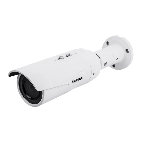
- Page 1 IB9389-EH-v2 IB9389-EHT-v2 Bullet Network Camera User ’s Manual 5MP • Outdoor • IP66 • IK10 • Day & Night • Smart Motion Detection WDR Pro • Smart Stream III • 50M Smart IR Rev. 1.0...
-
Page 2: Table Of Contents
VIVOTEK Table of Contents Overview ..................................Revision History ..............................4 Read Before Use ..............................4 Package Contents ..............................5 Symbols and Statements in this Document ......................5 Physical Description .............................. 6 Hardware Installation ............................. 8 Software Installation ............................. 20 Network Deployment ............................25 Ready to Use ................................ -
Page 3: Overview
VIVOTEK Storage ..............................153 Storage > NAS management ........................154 Storage > Content management ......................156 Appendix ..............................URL Commands for the Network Camera ....................159 Technology License Notice ........................434 Electromagnetic Compatibility (EMC) ....................... 435 Overview The IB9389 is an outdoor bullet network camera capable of 2560 x 1920 at 30 fps. With the VIVOTEK WDR Pro technology, the camera series is capable of capturing the highest quality images in both low light and high contrast environments. -
Page 4: Revision History
VIVOTEK Revision History ■ Rev. 1.0: Initial release. Read Before Use The use of surveillance devices may be prohibited by law in your country. The Network Camera is not only a high-performance web-ready camera but can also be part of a flexible surveillance system. -
Page 5: Package Contents
VIVOTEK Package Contents ■ IB9389-v2 ■ Screw pack, sun shield, desiccant bag. ■ Quick Installation Guide. WARNING: 1. IR lights emit from this product. 2. Use appropriate shielding or eye protection. Symbols and Statements in this Document INFORMATION: provides important messages or advices that might help prevent inconvenient or problem situations. -
Page 6: Physical Description
VIVOTEK Physical Description Outer View Sun shield Lens IR LEDs Inner View MicroSD card slot Reset button 6 - User's Manual... - Page 7 VIVOTEK NOTE: Some of the suffix syntax used in model naming are listed below: w/ heater for extreme weather Focal length w/ number w/ Remote focus lens w/ PoE repeater w/ High Dynamic Range functionality Model IB9389-EH-v2 IB9389-EHT-v2 Rating POE 42.5~57V , 0.3~0.23A POE 42.5~57V , 0.3~0.23A (12.95W) (12.95W) Screws...
-
Page 8: Hardware Installation
VIVOTEK Hardware Installation 1. Jot down the camera's MAC address for later reference. XXXXXX 0002D10766AD 2. Use a pencil to mark the drill hole positions on the wall or ceiling. 8 - User's Manual... - Page 9 VIVOTEK 3. Route cables through the wall or ceiling, and install the wall anchors. 4. Use the included screws to secure the wall bracket. User's Manual - 9...
- Page 10 VIVOTEK 5. Disassemble the waterproof cable gland. 6.Insert an Ehternet cable through the waterproof components. Note the maximum cable diameter. Ø 14mm Ø 5mm 10 - User's Manual...
- Page 11 VIVOTEK 7. Insert the RJ45 connector to the camera. 8. Install the cable gland components. User's Manual - 11...
- Page 12 VIVOTEK 9. Tighten the cable gland claw and hex nut using a hex wrench. 10. Install the camera to the wall-mount bracket and tighten the hex screws on the sides of the bracket. 12 - User's Manual...
- Page 13 VIVOTEK 11. Remove the M3 retention screw before opening the canister. . Keep the screw for later use. 12. Use both of your hands to hold and turn the front and the rear of the canister in opposite directions. Open the canister. IB9389-EHT-v2 User's Manual - 13...
- Page 14 VIVOTEK IB9389-EH-v2 13. Install a MicroSD card if onboard storage is preferred. 14 - User's Manual...
- Page 15 VIVOTEK 14. Replace the desiccant bag to avoid moisture inside the canister. 15. Install the front section of the canister by turing into position. IB9389-EHT-v2 User's Manual - 15...
- Page 16 VIVOTEK IB9389-EH-v2 16. Secure the canister by fastening the M3 screw you previously removed. 16 - User's Manual...
- Page 17 VIVOTEK 17. Please visit VIVOTEK’s website to Install the "Shepherd” software utility. The program will search for VIVOTEK Video Receivers, Video Servers or Network Cameras on the same LAN. Double-click on the camera’s MAC address to open a web console to the camera. Shepherd Browser 18.
- Page 18 VIVOTEK Max. 90° 19. When the adjustment to the shooting is done, tighten the retention screws. 18 - User's Manual...
- Page 19 VIVOTEK 20. Install the sun shield by fastening 2 included screws. When using the EHT model, enter the firmware menu to get the best image focus. Configuration > Media > Image > Focus -EHT Focus window Focus window User's Manual - 19...
-
Page 20: Software Installation
VIVOTEK Software Installation 21. Install the Shepherd utility, which helps you locate and configure your Network Camera in the local network. If your camera comes without the CD, go to VIVOTEK’s website, and locate the utility in the Downloads > Software page. 21-1. - Page 21 VIVOTEK 21-3. The program will search for all VIVOTEK network devices on the same LAN. 21-4. After a brief search, the installer window will prompt. Click on the MAC and model name that matches the one printed on the product label. You can then double-click on the address to open a management session with the Network Camera.
- Page 22 VIVOTEK Forceful Password Configuration 22. The first time you log in to the camera, the firmware will prompt for a password configuration for security concerns. 22-1. Since your camera is used for the first time, there is no password. Enter “root” as the user name, and nothting for the password.
- Page 23 VIVOTEK Some, but not all special ASCII characters are supported: !, $, %, -, ., @, ^, _, and ~. You can use them in the password combination. 22-3. Another prompt will request for the password you just configured. Enter the password and then you can start configure your camera and see the live view.
- Page 24 VIVOTEK Hardware Reset The reset button is used to reset the system or restore the factory default settings. Sometimes resetting the system can return the camera to normal operation. If the system problems remain after reset, restore the factory settings and install again. Reset: Press the recessed reset button.
-
Page 25: Network Deployment
VIVOTEK Network Deployment General Connection (PoE) When using a PoE-enabled switch The Network Camera is PoE-compliant, allowing transmission of power and data via a sin- gle Ethernet cable. Follow the below illustration to connect the Network Camera to a PoE- enabled switch via Ethernet cable. -
Page 26: Ready To Use
VIVOTEK Ready to Use 1. A browser session to the Network Camera should prompt as shown below. 2. You should be able to see live video from your camera. You may also install the 32-channel recording software in a deployment consisting of multiple cameras. For its installation details, please refer to its related documents. - Page 27 VIVOTEK Internet connection via a router Before setting up the Network Camera over the Internet, make sure you have a router and follow the steps below. 1. Connect your Network Camera behind a router, the Internet environment is illustrated below. Regarding how to obtain your IP address, please refer to Software Installation on page 20 for details.
- Page 28 VIVOTEK For example, your router and IP settings may look like this: IP Address: internal port IP Address: External Port (Mapped Device port on the router) Public IP of router 122.146.57.120 LAN IP of router 192.168.2.1 192.168.2.10:80 122.146.57.120:8000 Camera 1 192.168.2.11:80 122.146.57.120:8001 Camera 2...
-
Page 29: Accessing The Network Camera
VIVOTEK Accessing the Network Camera This chapter explains how to access the Network Camera through web browsers, RTSP players, 3GPP-compatible mobile devices, and VIVOTEK recording software. Using Web Browsers Use Installation Wizard 2 (IW2) to access the Network Cameras on LAN. If your network environment is not a LAN, follow these steps to access the Netwotk Camera: ®... - Page 30 VIVOTEK ► By default, the Network Camera is not password-protected. To prevent unauthorized access, it is highly recommended to set a password for the Network Camera. For more information about how to enable password protection, please refer to Security on page 106.
- Page 31 VIVOTEK IMPORTANT: • Currently the Network Camera utilizes a 32-bit ActiveX plugin. You CAN NOT open a management/view session with the camera using a 64-bit IE browser. • If you encounter this problem, try execute the Iexplore.exe program from C:\Windows\ SysWOW64.
-
Page 32: Using Rtsp Players
VIVOTEK Using RTSP Players To view the streaming media using RTSP players, you can use one of the following players that support RTSP streaming. VLC media player VLC media player mpegable Player 1. Launch the RTSP player. 2. Choose File > Open URL. A URL dialog box will pop up. pvPlayer 3. -
Page 33: Using 3Gpp-Compatible Mobile Devices
VIVOTEK Using 3GPP-compatible Mobile Devices To view the streaming media through 3GPP-compatible mobile devices, make sure the Network Camera can be accessed over the Internet. For more information on how to set up the Network Camera over the Internet, please refer to Setup the Network Camera over the Internet on page To utilize this feature, please check the following settings on your Network Camera: 1. -
Page 34: Using Vivotek Recording Software
VIVOTEK Using VIVOTEK Recording Software Visit our website for download the VAST recording software that provides simultaneous monitoring and video recording for multiple Network Cameras. Please install the recording software; then launch the program to add the Network Camera to the Channel list. For detailed information about how to use the recording software, please refer to the user’s manual of the software or download it from http://www.vivotek.com. -
Page 35: Main Page
VIVOTEK Main Page This chapter explains the layout of the main page. It is composed of the following sections: VIVOTEK INC. Logo, Host Name, Camera Control Area, Configuration Area, Menu, and Live Digital zoom is only available in the Liveview profile. Video Window. - Page 36 VIVOTEK Configuration Area Client Settings: Click this button to access the client setting page. For more information, please refer to Client Settings on page 40. Configuration: Click this button to access the configuration page of the Network Camera. It is suggested that a password be applied to the Network Camera so that only the administrator can configure the Network Camera.
- Page 37 VIVOTEK PTZ Panel: This Network Camera supports “digital“ (e-PTZ) pan/tilt/zoom control, which allows roaming a smaller view frame within a large view frame. Please refer to PTZ settiings on page 121 for detailed information. Global View: Click on this item to display the Global View window. The Global View window contains a full view image (the largest frame size of the captured video) and a floating frame (the viewing region of the current video stream).
- Page 38 VIVOTEK Video Control Buttons: Depending on the Network Camera model and Network Camera configuration, some buttons may not be available. Snapshot: Click this button to capture and save still images. The captured images will be displayed in a pop-up window. Right-click the image and choose Save Picture As to save it in JPEG (*.jpg) or BMP (*.bmp) format.
- Page 39 VIVOTEK ■ The following window is displayed when the video mode is set to MJPEG: Video Title Time 2018/07/25 17:08:56 Video (HTTP-V) Title and Time Video 17:08:56 2018/07/25 Video Control Buttons Video Title: The video title can be configured. For more information, please refer to Media > Image on page 64.
-
Page 40: Client Settings
VIVOTEK Client Settings This chapter explains how to select the stream transmission mode and saving options on the local computer. When completed with the settings on this page, click Save on the page bottom to enable the settings. H.265/H.264 Protocol Options H.264 Protocol Options Depending on your network environment, there are four transmission modes of H.264 streaming: UDP unicast: This protocol allows for more real-time audio and video streams. - Page 41 VIVOTEK MP4 Saving Options Users can record live video as they are watching it by clicking Start MP4 Recording on the main page. Here, you can specify the storage destination and file name. Folder: Specify a storage destination on your PC for the recorded video files. The location can be changed.
- Page 42 VIVOTEK Joystick settings Enable Joystick Connect a joystick to a USB port on your management computer. Supported by the plug-in (Microsoft’s DirectX), once the plug-in for the web console is loaded, it will automatically detect if there is any joystick on the computer. The joystick should work properly without installing any other driver or software.
- Page 43 VIVOTEK Buttons Configuration In the Button Configuration window, the left column shows the actions you can assign, and the right column shows the functional buttons and assigned actions. The number of buttons may differ from different joysticks. Please follow the steps below to configure your joystick buttons: 1.
- Page 44 VIVOTEK Buttons Configuration Click the Configure Buttons button, a window will prompt as shown below. Please follow the steps below to configure your joystick buttons: 1. Select a button number from the Button # pull-down menu. Tips: If you are not sure of the locations of each button, use the Properties window in the Game Controllers utility.
-
Page 45: Configuration
VIVOTEK Configuration Click Configuration on the main page to enter the camera setting pages. Note that only Administrators can access the configuration page. VIVOTEK provides an easy-to-use user interface that helps you set up your network camera with minimal effort. In order to simplify the user interface, detailed information will be hidden unless you click on the function item. -
Page 46: System > General Settings
VIVOTEK System > General settings This section explains how to configure the basic settings for the Network Camera, such as the host name and system time. It is composed of the following two columns: System, and System Time. When finished with the settings on this page, click Save at the bottom of the page to enable the settings. - Page 47 VIVOTEK System time Keep current date and time: Select this option to preserve the current date and time of the Network Camera. The Network Camera’s internal real-time clock maintains the date and time even when the power of the system is turned off. Synchronize with computer time: Select this option to synchronize the date and time of the Network Camera with the local computer.
- Page 48 VIVOTEK Western Argentina Summer Time (WARST) is 3 hours behind the prime meridian all year. There is a dummy fall-back transition on December 31 at 25:00 daylight saving time (i.e., 24:00 standard time, equivalent to January 1 at 00:00 standard time), and a simultaneous spring-forward transition on January 1 at 00:00 standard time, so daylight saving time is in effect all year and the initial WART is a placeholder.
-
Page 49: System > Homepage Layout
VIVOTEK System > Homepage layout This section explains how to set up your own customized homepage layout. General settings This column shows the settings of your hompage layout. You can manually select the background and font colors in Theme Options (the second tab on this page). The settings will be displayed automatically in this Preview field. - Page 50 VIVOTEK Theme Options Here you can change the color of your homepage layout. There are three types of preset patterns for you to choose from. The new layout will simultaneously appear in the Preview filed. Click Save to enable the settings.
- Page 51 VIVOTEK ■ Follow the steps below to set up the customized homepage: 1. Click Custom on the left column. 2. Click the field where you want to change the color on the right column. Color Selector Custom Pattern 3. The palette window will pop up as shown below. 4.
-
Page 52: System > Logs
VIVOTEK System > Logs This section explains how to configure the Network Camera to send the system log to a remote server as backup. Log server settings Follow the steps below to set up the remote log: 1. Select Enable remote log. 2. - Page 53 VIVOTEK You can install the included VAST recording software, which provides an Event Management function group for delivering event messages via emails, GSM short messages, onscreen event panel, or to trigger an alarm, etc. For more information, refer to the VAST User Manual. VIVOTEK Network Cameras Internet 3G Cell phone...
- Page 54 VIVOTEK Access log Access log displays the access time and IP address of all viewers (including operators and administrators) in a chronological order. The access log is stored in the Network Camera’s buffer area and will be overwritten when reaching a certain limit. Set Parameter log VADP log contains the history of changes made to system parameters such as recording, imaging parameters, and all other parameters.
-
Page 55: System > Parameters
VIVOTEK System > Parameters The View Parameters page lists the entire system’s parameters. If you need technical assistance, please provide the information listed on this page. User's Manual - 55...
Need help?
Do you have a question about the VIVOTEK IB9389-EH-v2 and is the answer not in the manual?
Questions and answers