Table of Contents
Advertisement
Quick Links
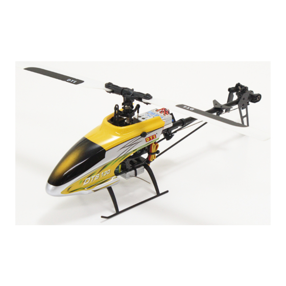
DTS130
285mm
110mm
75mm
320mm
75mm
132g
5800KV
GWY E10 10A
GWY 2013S
GWY S4P
*3pcs
GWY S3S
*1pcs
GWY 6TL/V2 2.4GHz
2S 7.4V 400mAh 25C
Before this model has being significantly changed to another new version, the parts, appearance and the existing version can be developed and
modified that would lead to a slight difference from the original design. DTS reserve ALL the Rights of change of parts and contents WITHOUT
specified notification.
AHSS
Specifications
Length:285mm
Height:110mm
Width:75mm
Main Rotor Diameter: 320mm
Tail Rotor Diameter: 75mm
Weight:Approximately 132g
5800KV Brushless Motor
GWY E10 10A Brushless Motor ESC
GWY 2013S 3-axis Gyro
GWY S4P Swash Servos*3
GWY S3S Tail Servos) * 1
GWY 6TL/V2 2.4GHz 6-Channel Transmitter
2S 7.4V 400mAh 25C Li-polymer Battery
DTS
R
D T S
Advertisement
Table of Contents

Related Manuals for DTS DTS130


Summary of Contents for DTS DTS130
- Page 1 Before this model has being significantly changed to another new version, the parts, appearance and the existing version can be developed and modified that would lead to a slight difference from the original design. DTS reserve ALL the Rights of change of parts and contents WITHOUT...
-
Page 2: Table Of Contents
Foreword Thank you for choosing DTS's product. For better understanding and usage of DTS 130, please read the manual carefully before installation and operation. For your convenience of adjustment, maintenance and other operation, please keep the manual in proper manner. For further information, please visit Zonda Hobby official website: http://www.zondahobby.com,www.zondahobby.com.cn... -
Page 3: Statement
5.Do Not re-equip, upgrade or repair your helicopter with the accessories outside the DTS parts catalog in order to ensure the safety of the model structure! 6.Keep people and objects away from the spinning unit and parts in case of damage or injury! -
Page 4: Packaging Contents
Packaging Contents Please check the parts and accessories in the package. In the event of defective or missing parts, please contact the retailer for help. 1. DTS130 2. 2.4GHz 6-Channel Transmitter 3. 2S & 3S Battery Charger 4. Power Supply: 1.5A 100-240V AC-12V DC(UK\Europe\USA\Austrilia) 5. -
Page 5: Helicopter Parts
Helicopter Parts Elevator Servo Aileron Servo GWY2013S 3-axis Gyro Pitch Servo Rudder Servo Li-Po Battery Brushless ESC Brushless Motor... -
Page 6: 6Tl /Ah6Ttransmitter Setting Module
6TL Transmitter Setting Module SYS.MENU 1/16 MODEL SELECT 2/16 MODEL NAME 3/16 MODEL TYPE 4/16 COPY/RESET DTS130 DTS130 Helicopter 5/16 TRIM SETP 6/16 SWASH TYPE 7/16 STICK MODE 8/16 TRANSFER DATA STEP NORM 90 THRO AILE ELEV RUDD 9/16 THRO CUT&REV... - Page 7 AH6T Transmitter Setting Module DTS 130 DTS 130 1 Servo Normal Model Reset Model Copy Switch Select Hold:sH Gov:Inh Thr:4 Ele:0 Bind:Inh F.M:sB Ail:0 Rud:0 Gyro:Inh Gear:sA Trim TYPE:Common Mix:Inh Warnings Trainer Fail Safe Inhibit Throttle POS: -100 Mode: H-FHSS...
-
Page 8: Pre-Flight Controls Test
Pre-Flight Controls Test 1.Control Test: Throttle Push up the throttle stick slowly until the motor rotate. Make sure that the motor rotates clockwisely and the main blade rotates anti-clockwisely. Throttle Position: Right Throttle Position: Left Please don't push the throttle stick upward over 1/5. The motor will spins at high velocity if the throttle stick is over pushed. - Page 9 3.Control Test: Pitch (only aerobatics use) Swashplate's upward and downward movement Throttle Position: Left Throttle Position: Right Throttle Position: Right Throttle Position: Left Throttle Position: Left Throttle Position: Right 4.Control Test: Aileron Swashplate's Left and Right declining movement (The rudder's control is the same in both left and right-hand throttle transmitter) Rear View Rear View Rear View...
- Page 10 5.Control Test: Rudder Tail rotor blades pitch change (The rudder's control is the same in both left and right-hand throttle transmitter) 6. Gyro adjustment Disconnect the connection between ESC and motor, turn on the power of the transmitter and helicopter, move the pushrod to check the sercos direction.
-
Page 11: Rotor Housing Assemble Procedure
Rotor Housing Assemble Procedure Apply amount of T43 thread-locking fluid Apply little amount lubricants CAUTION Big Diameter Apply a little amount of T43 thread lock when fixing a metal part. Do not spill over thread-locking fluid which may jam the blade rotation. Description Specification need... -
Page 12: Power System Assemble Procedure
Power System Assemble Procedure Apply amount of T43 thread-locking fluid Apply little amount lubricants CAUTION Place the servos, connect the servo arms to the servos with screws horizontally. Follow the diagram sequence to install the other parts. Description Specification need Philips Pan Head Bolt M1.2*6 Philips Pan Head Bolt... -
Page 13: Mainframe Assemble Procedure
Mainframe Assemble Procedure Apply amount of T43 thread-locking fluid Apply little amount lubricants CAUTION Apply a little amount of T43 thread lock when fixing a metal part to the motor mount. Description Specification need Anti Rotation Bracket Servo Arm Complete installation Philips Head Screw M1.7*4 Philips Head Screw... -
Page 14: Tail Case Assemble Procedure
Tail Case Assemble Procedure Apply amount of T43 thread-locking fluid Apply little amount lubricants CAUTION Place the bevel gear into the drive gear properly. 2 sets are required. *Complete installation* Before After Description Specification need Bevel Gear A Drive Gear Ball Bearing 2* 5*2.5 Ball Bearing... -
Page 15: Tail Boom Assemble Procedure
Tail Boom Assemble Procedure Apply amount of T43 thread-locking fluid Apply little amount lubricants Place the tail boom inside the tail case. CAUTION nstall the parts base on the diagram above sequentially. Lock the fin mount cap after Complete installation fixing the pushrod guide set. -
Page 16: Tail Rotor Blade Assemble Procedure
Tail Rotor Blade Assemble Procedure Apply amount of T43 CAUTION thread-locking fluid Apply a little amount of T43 Apply little amount lubricants thread lock when fixing M1.4*3 screw parts. Make sure the tail rotor blade grips rotate smoothly. Description Specification need Hexagon Socket Head Screw M2*8... -
Page 17: Tail Boom Case Assemble Procedure
Tail Boom Case Assemble Procedure Apply amount of T43 thread-locking fluid Apply little amount lubricants CAUTION Torque Rod Place the bevel gear into the tail boom. Make sure the drive gear can reach the bevel gear. Install the parts base on the diagram above sequentially. -
Page 18: Mainframe Assemble Procedure
Mainframe Assemble Procedure Apply amount of T43 thread-locking fluid Apply little amount lubricants CAUTION Install the main blades, tail boom support rod and tail boom case to Pushrod the mainframe sequentially. Tail Boom Support Rod (Completed) Pushrod Description Specification need Hexagon Socket Head Bolt M2*10 Philips Head Screw... -
Page 19: Canopy Assemble Procedure
Canopy Assemble Procedure CAUTION Install the gyro, ESC and other electronic devices to the mainframe. After finishing the control test and gyro adjustment, install the canopy (holding by the canopy mount rod). Completed installation Enjoy your flight after finishing the control test, gyro adjustment and the canopy installation! -
Page 20: Exploded View
Exploded View... - Page 21 Parts List Description Specification Description Specification need need Main Blade Horizontal Fin Mount Hexagon Socket Head Bolt M2*10 4g Servo M1.6*5 Tail Boom 6*150 Philips Pan Head Bolt Pushrod Horizontal Fin Mount Cap Horizontal Fin 2.5* 4.5*2 Damper: Ring Hexagon Socket Head Screw M2*8 Spindle 2.5*29.8...
-
Page 22: Spare Parts List
Spare Parts List DTS004389 DTS004390 DTS004391 DTS004392 Pushord Set Main Rotor Blade Grip Set Spindle Swashplate Set DTS004393 DTS004394 DTS004395 DTS004396 Rotor Housing Set Tail Rotor Pitch Control Tail drive Gear set Servo Arm Set Slider Set DTS004397 DTS004398 DTS004399 DTS004400 Tail Rotor Pitch Lever Set Main Blade Set: Plastic Blade... - Page 23 DTS004413 DTS004414 DTS004415 DTS004416 Tail Boom Case Main Frame Set Servo/Fin mount and Tail Boom Brace/Support Set Pushrod Guide set DTS004417 DTS004418 DTS004419 DTS004420 Battery Tray Landing Gear Set Stabilizer/Fin set Pinion Gear: 9T DTS004421 DTS004422 DTS004423 DTS004424 Thrust Bearing Pinion Gear: 10T Bearing: 2x5x2 Flanged Bearing...
- Page 24 GWY004316 GWY005449 GWY005451 GWY004718 10A Heli Brushless ESC Brushless ESC: 10A 2S Heli GWY 6TL\V2 2.4G GWY2013s:Small Receiver-6ch, Remote Receiver, Transmitter, 6CH, AHSS, Silver Flybarless System; AHSS 2.4G,FHSS GWY006500 GWY006227 G02S Flybarless Control 2.4GHz, AH6T 6CH System Gyro Transmitter...
- Page 25 DTS130 www.zondahobby.com, www.zondahobby.com.cn 6TL/AH6T...
- Page 26 :-10 50 )
- Page 27 2.2.4G 3.2-3 5.SD 6.7.4V 400mAh DTS 130 6TL - 2.4GHz 6 AH6T - 2.4GHz 6 GWY2013S - G02S - 2S & 3 S : 400mAh 2S 7.4V...
- Page 28 GWY2013S...
- Page 29 SYS.MENU 1/16 MODEL SELECT 2/16 MODEL NAME 3/16 MODEL TYPE 4/16 COPY/RESET DTS130 DTS130 Helicopter 5/16 TRIM SETP 6/16 SWASH TYPE 7/16 STICK MODE 8/16 TRANSFER DATA STEP NORM 90 THRO AILE ELEV RUDD 9/16 THRO CUT&REV 10/16 FAIL SAFE 11/16 POWER SETTING 12/16 LCD CONTRAST <125%...
- Page 30 AH6T DTS 130 DTS 130 1 Servo Normal Model Reset Model Copy Switch Select Hold:sH Gov:Inh Thr:4 Ele:0 Bind:Inh F.M:sB Ail:0 Rud:0 Gyro:Inh Gear:sA Trim TYPE:Common Mix:Inh Warnings Trainer Fail Safe Inhibit Throttle POS: -100 Mode: H-FHSS Throttle:Over Stunt1:Act Stunt2:Act...
- Page 31 飞行前舵面的检查(出厂设置) 1.舵面检查:油门 将油门摇杆慢慢的往上推,直到马达转动即可。此时请确认马达为逆时针方向旋转,而主旋翼则为顺时针方向旋转。 右手油门 左手油门 测试时,请勿将油门摇杆向上推动到超过1/5,否则油门摇杆推得过多,马达会急速旋转,可能会造成机体或自身的伤害! 除非是正式飞行,否则在室内进行维修保养或调整工作时,我们十分强烈的建议玩家将无刷马达与电调的连接线断开,以 防止马达意外的旋转造成危险! 2.舵面检查:升降舵 倾斜盘前后倾斜 右手油门 左手油门 右手油门 左手油门 右手油门 左手油门...
- Page 32 3.舵面检查:螺距(在特技模式下) 倾斜盘上下运动 右手油门 左手油门 右手油门 左手油门 右手油门 左手油门 4.舵面检查:副翼 倾斜盘左右倾斜 (右手油门和左手油门发射机的副翼摇杆操作相同) 后视图 后视图 后视图...
- Page 33 5.舵面检查:方向舵 尾旋翼角度左右变化 (右手油门和左手油门发射机的方向舵 摇杆操作相同) 6.陀螺方向修正 断开调速器与马达的连接,开启发射器和直升机的电源,移动所有摇杆检查伺服方向。 1.如果手动使直升机围绕主轴转动,陀螺仪则会操控尾舵机抵消转动的方向动作。 例:机尾向右转,那么陀螺会操控尾舵进行左舵修正。图A 2.手持直升机,并向某方向倾斜直升机机体,此时倾斜盘应该朝机体的相反方向倾斜。 例:当直升机向前方倾斜时,倾斜盘应该向后倾斜,当直升机向后方倾斜时,倾斜盘应该向前倾斜,图B。 如果将直升机横向倾斜,倾斜盘应该向相反的方向修正,图C。 当机体恢复初始水平位置,倾斜盘也应该同样回到初始位置。 图A 图B 倾斜盘方向 倾斜盘方向 机体倾斜方向 机体倾斜方向 图C 倾斜盘方向 机尾转动方向 倾斜盘方向 机体倾斜方向...
- Page 34 M1.6*5 2.5* 4.5*2 2.5*29.8 2.5* 4.5*0.5 2.5* 6*1.8 3* 4.5*1.6 5* 6*0.1 2.5* 6*3...
- Page 35 M1.2*6 M1.2*2 3* 6.5*2.5 3*65.8 M1.7*4 3* 6*2.5 M1.4*5 M2*3...
- Page 36 M1.7*4 M1.4*5 M2*5 M1.2*3 M2*10 M1.4*5...
- Page 37 2* 5*2.5 3* 6*2 3* 4*1.5 S 2.5*1.75 1.95* 2.55*4.4 1.2* 1.95*4.9 M1.2*9 2*35 2* 5*2.5 M1.2*3...
- Page 38 M1.7*4 M1.2*3 M1.4*6 S 2.5*1.75 6*150 M1.2*7 M1.7*4...
- Page 39 M1.4*3 M2*8 M1.4*3 2* 5*2 2.2* 3.8*0.5 2* 5*2.5 0.8*4...
- Page 40 M1.4*5 M1.2*3 M1.2*118...
- Page 41 M2*10 M1.4*5 M1.2*4...
- Page 44 M2*10 M1.6*5 6*150 2.5* 4.5*2 M2*8 2.5*29.8 2.5* 4.5*0.5 M1.4*3 2.5* 6*1.8 2* 5*2 2.2* 3.8*0.5 3* 4.5*1.6 5* 6*0.1 2.5* 6*3 0.8*4 M1.2*2 3* 6.5*2.5 3* 6*2 0.8*20 2* 4*8.3 1.5*3.5 3* 65.5 1.95* 2.55*4.4 1.2* 1.95*4.9 M1.7*4 M1.2*9 3* 6*2.5 M1.4*5 3* 4*1.5...
- Page 45 DTS004389 DTS004390 DTS004391 DTS004392 DTS004393 DTS004394 DTS004395 DTS004396 DTS004397 DTS004398 DTS004399 DTS004400 DTS004403 DTS004404 DTS004401 DTS004402 DTS004405 DTS004406 DTS004407 DTS004408 DTS004409 DTS004410 DTS004411 DTS004412...
- Page 46 DTS004413 DTS004414 DTS004415 DTS004416 DTS004417 DTS004418 DTS004419 DTS004420 DTS004421 DTS004422 DTS004423 DTS004424 (2*5*2) DTS004427 DTS004428 DTS004425 DTS004426 ( 3* 6*2.5) ( 3* 6*2) ( 2* 5*2.5) ( 2.5* 6*1.8) DTS004429 DTS004430 DTS004453 GWY004447 GWY004580 GWY004279 GWY005467 GWY4T 4g GWY4P 4g...
- Page 47 GWY004316 GWY005449 GWY005451 GWY004718 10A Heli Brushless ESC GWY2013S GWY006500 GWY006227 G02S AH6T 2.4GHz 6...
- Page 48 Global Distribution Office: Zonda Hobby Technologies Electronic Limited Room 1, 1/F, Kam Hon Industrial Building, No.8 Wang Kwun Road, Kowloon Bay, Kowloon, Hong Kong Tel: (852) 3160 8886 Fax: (852) 3160 8884 Official Website: www.zondahobby.com / www.zondahobby.com.cn ※本型号机型在尚未进行重大改版之前,配件可能进行调整,外观、型号可能稍有不同。GWY保留配件内容更改权,并不另行通知。 Before this model has being significantly changed to another new version, the parts, appearance and the existing version can be developed and modified that would lead to a slight difference from the original design.
Need help?
Do you have a question about the DTS130 and is the answer not in the manual?
Questions and answers