
Related Manuals for Geovent WE-55


Summary of Contents for Geovent WE-55
- Page 1 I N S T R U C T I O N M A N U A L Wood dust extraction W E - 5 5 www.geovent.com Version 1.0 01.08.2022...
-
Page 2: Table Of Contents
Contents The device has been constructed and produced on the basis of following harmonized standards: 1 Introduction • PN-EN ISO 12100:2012 2 Purpose and use “Safety of machinery. Basic concepts, general princi- 3 Manufacturer’s reservation ples for design. Risk assessment and risk reduction”. 4 Technical data 5 Unit and function •... -
Page 3: Technical Data
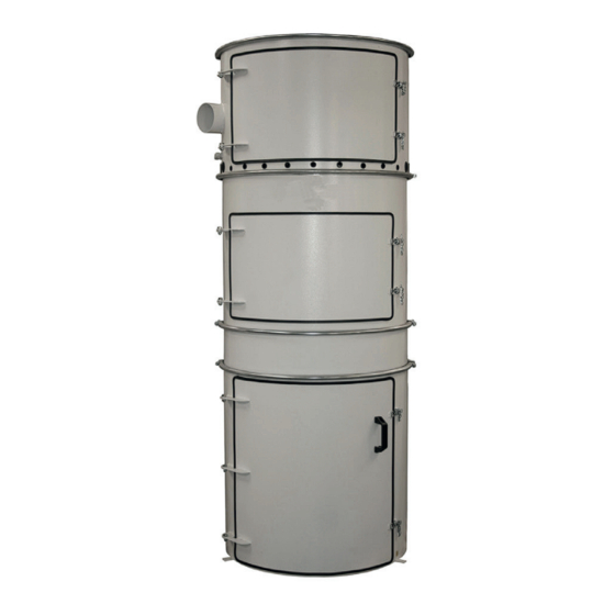
D. The device is protected against mechanical damage The unit consists of four modules which are connected E. Waste bags and filters are protected and inspected together with tension bands: regularly Upper part (bilde til venstre under) F. The device is not used to filter air containing: The top module houses the fan and shaker motor, as •... - Page 4 Second top part (picture in the middle above) Here is the suspension ring for filter and filter. The top two modules cannot be rotated relative to each other. Inlet module (picture on the right above) This is rotatable, and the inlet can be rotated so that the inlet pipe is placed appropriately.
- Page 5 We recommend the use of high-vacuum pipes and damper/flap valves with microswitches. We recommend using high vacuum tubes and parts to avoid leaks. The unit is a high-pressure unit within the field of chip extraction, and spiro pipes are not accept- able solutions.
-
Page 6: Installation And Start-Up
6 Installation and start The WE-5,5 / D chip extractor is designed for use in a closed room. It should be placed stably on an even floor surface. It is important to have access to air for air circu- lation and cooling, and that the user has enough space to change the filter and waste bag. -
Page 7: Use, Application And Alarms
A silencer (900/1200 mm – Ø200/250) and a spiro for For emptying the bag; Open the bottom door, pull out the the outdoors are recommended on the return (Ø200/250 trolley with the waste bag to change the bag. mm recommended). Electrical work must be carried out Clean any capacitive sensor. -
Page 8: Maintenance
Engine overheating Rubber suspension for filter bags. 3 suspensions + mo- Check for damage to the engine. Check cause. tor shaft from shaker motor holds filter bags. The rub- ber is exposed to relatively hard loads and has a limited Bad suction - incorrect direction of rotation of fan lifespan.Vi anbefaler å... -
Page 9: Transport And Storage
Maintenance and service plan for the unit, see sugges- Always check the device upon receipt!!!! Check for tions below: transport damage, damage to packaging, to the surface Improper handling of the device during transport, load- Maintenance and recommended service ing and reloading can cause: - Damage to unit housing, fan, control cabinet, Interval automatics. -
Page 10: Electrical Connection Diagram 3 X 400
14 Electrical connection diagram for 14 Elektriske koblingsskjema for 3 x 400 V 3 x 400 V (be om separate skjemaer, dersom de er vanskelig å lese) (ask for separate forms, if they are diffi cult to read) Side 15 av 20... - Page 11 Side 16 av 20 11 11...
-
Page 12: Electrical Connection Diagram 3 X 230
15 Electrical connection diagram for 15 Elektriske koblingsskjema for 3 x 230 V 3 x 230 V (be om separate skjemaer, dersom de er vanskelig å lese) (ask for separate forms, if they are diffi cult to read) Side 17 av 20... - Page 13 Side 18 av 20...
-
Page 14: Simple System Description
16 Simple system description of chip ex- Itek offers complete service agreements with inspection and parts replacement. traction WE-5.5 (5.5 kW) The WE units have been developed for chip and chip ex- 17 Usage poster – hung up in the storage traction in ductwork rooms and smaller carpentry work- room shops with a focus on the following parameters:... - Page 15 • Check that the bottom door is tight and free of dust, otherwise the bag will be sucked into the filter and give an alarm. • Filters are changed at least once a year • Steady red alarm light means that the bag is full, or that the bag is being sucked up •...
- Page 16 6.0 EC declaration of conformity according to Appendix IIA HOVEDGADEN 86 • DK-8831 LØGSTRUP (+45) 8664 2211 • salg@geovent.dk The producer hereby declares that: Authorized to collect the technical dossier: Product: Chip extraction system Lise Cramer Model: WE 5,5 is in accordance with the following directives and stan-...
Need help?
Do you have a question about the WE-55 and is the answer not in the manual?
Questions and answers