Table of Contents
Advertisement
Quick Links
Advertisement
Table of Contents

Related Manuals for Citronic CLP122DSP-B


Summary of Contents for Citronic CLP122DSP-B
- Page 2 CONTENTS ____________________________________________________ A. INPUT CHANNEL SECTION……………….. B. STEREO CHANNEL SECTION……………. C. MASTER SECTION………………………….. D. MIXER OUTPUT SECTION…………………. E. POWER SECTION…………………………… F. INSTALLATION……………………………… G. CONNECTION……………………………….. H. APPENDIX……………………………………. 11 I. BLOCK DIAGRAM…………………………… 13 There are no user serviceable parts inside the unit. Do not open the unit.
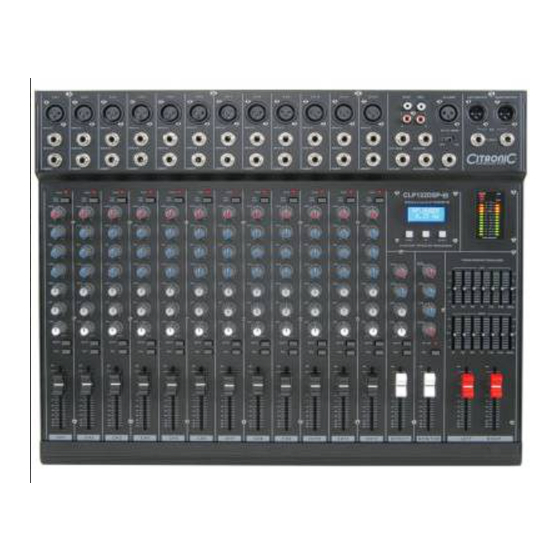
- Page 3 A. INPUT CHANNEL SECTION 1. BALANCED INPUT (MIC) Mic balanced inputs accept a standard XLR male connector. +48V Phantom Power is available on XLR inputs. 2. LINE INPUT The 1/4”TRS jack socket is designed to accept a high impedance input signal.(eg.
- Page 4 5. PAD (-20dB) E. SPECIFICATIONS Attenuates the signal by 20dB when pushed in INPUT CHANNELS 6. GAIN Input Electronically balanced/unbalanced XLR or 6.3mm jack Adjusts the input sensitivity. Too high a value can cause distortion, too low a value can Mic E.I.N.
- Page 5 SCHEMATIC 20. EFFECT MUTE Mutes the effect signal feed to the main mix 21. EFFECT PFL Pre-Fader Listen for EFFECT signal. Feeds the effected signal through to the headphones and level meters for monitoring and isolated signal adjustment 22. EFFECT FADER Adjusts the level of internal delay or external effect signal routed to the main mix.
- Page 6 Main mix signal outputs via balanced XLR or unbalanced 6.3mm jack 47. PHANTOM POWER Switch Engages +48Vdc phantom power to each XLR input for condenser microphones etc. 48. AMPLIFIER POWER Switch Switches mains power on/off 49. IEC Mains inlet 230V 50Hz © Citronic 2009...
Need help?
Do you have a question about the CLP122DSP-B and is the answer not in the manual?
Questions and answers