Lincoln industrial A Series Operator's Manual
Hide thumbs
Also See for A Series:
- Manual (12 pages) ,
- Instructions manual (9 pages) ,
- Installation manual (8 pages)
Advertisement
Quick Links
SPECIFICATIONS
Electrical Requirements
Model 94812 ............................ 12 VDC @ 3.5 amps
Model 94824 ............................ 24 VDC @ 2 amps
Enclosure Rating ....................... IP 54 - Protected from water
On Time ..................................... 2 minutes minimum
Off Time .................................... 1 hour minimum
Pump Output ............................ 0.146 cu. in./min (2.4 cm/min)
Outlet Connection .................... 1/8" NPT (female)
Maximum Recommended
Operating Pressure ............... 3600 psi (248 bar)
Reservoir Capacity ................... 488 cu. in. (8000 cc)
Lubricant ................................... Greases up to NLGI grade 2
Temperature Range .................. - 13
Pressure Relief Valve ............... 4000 psi +/- 250 psi
NOV - 96
OWNER/OPERATOR MANUAL
sprayed in all directions.
30 minutes maximum
in 2 minute increments
15 hours maximum
in 1 hour increments
(depending on the operating
temperature and type of lubricant)
°
°
°
F(-25
C) to +158
F(+70
(276 bar) +/- (17 bar)
One Lincoln Way
St. Louis, Missouri 63120-1578
(314) 679-4200
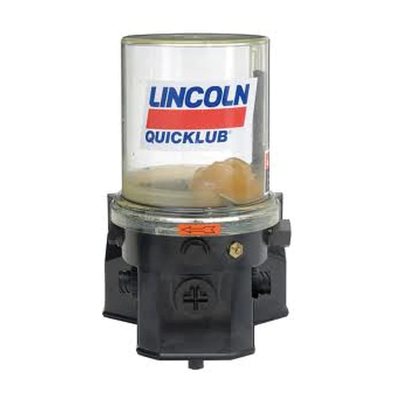
ELECTRIC GREASE PUMP
DESCRIPTION
The chassis lube pump is electrically operated and used in
a progressive type centralized lubrication system.
pump consists of a pump housing, electric gear motor, a
timer and a plastic reservoir with stirring paddle. The high
operating pressure allows the pump to supply lubricant up
to NLGI #2 grease.
MOUNTING THE PUMP
Select an easily accessible place of installation which allows
access to the timer and lubricant reservoir filler fitting. The
pump must be mounted vertically on an even surface by
means of three bolts. (See Fig. 1 on page 3.)
TO FILL RESERVOIR
Fill the reservoir through the grease fitting located at the
base of the reservoir, using a hand operated grease pump.
Refill reservoir when grease reaches "MIN" mark located on
the reservoir.
Fill the reservoir up to the "MAX" mark
located on the reservoir.
TO PRIME SYSTEM
Pump & Supply Line: After reservoir has been filled with
recommended lubricant, loosen the supply line fitting.
Operate the pump until lubricant flows from outlet, then
tighten fitting.
°
C)
Feed Lines: Pre-fill each feed line with lubricant before
connecting to outlet of divider valve and bearing.
Copyright 1996
Printed in U.S.A.
Models 94812, 94824
CHASSIS LUBE
Series "A"
- Q3
- Q3
- Q3
Section
Page
FORM 402724
The
- Q3
- Q3
- 8
- 8
- 8
- 8
- 8
Advertisement

Related Manuals for Lincoln industrial A Series


Summary of Contents for Lincoln industrial A Series
- Page 1 Models 94812, 94824 CHASSIS LUBE ELECTRIC GREASE PUMP Series “A” OWNER/OPERATOR MANUAL DESCRIPTION The chassis lube pump is electrically operated and used in a progressive type centralized lubrication system. pump consists of a pump housing, electric gear motor, a timer and a plastic reservoir with stirring paddle. The high operating pressure allows the pump to supply lubricant up to NLGI #2 grease.
- Page 2 Page 2 Form 402724...
- Page 3 ELECTRICAL CONNECTIONS Connect black power cord as follows: Red wire connects to 8 amp fuse then to Battery (+). White wire connects to Battery (-). Blue wire connects to 8 amp fuse, to ignition switch, then to Battery (+). PARTS LIST REMOTE MANUAL LUBE PUSHBUTTON ITEM DESCRIPTION...
- Page 4 TIMER OPERATION SERVICE PARTS/KITS The Off timer begins accumulating time when the PART QTY. DESCRIPTION ITEM ignition switch closes. When the Off timer reaches the preset value, the pump will turn on. The pump remains activated for the period of time that is pre- 5 0 4 5 Grease fitting set on the On timer.
Need help?
Do you have a question about the A Series and is the answer not in the manual?
Questions and answers