Table of Contents
Advertisement
Quick Links
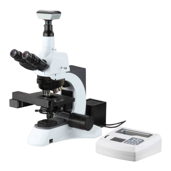
Motorized Microscope
With Auto-Focus System
User Manual
BestScope International Limited
This manual is for BS-2080D microscope. To ensure the safety, obtain optimum
performance and to familiarize yourself fully with the use of this microscope, it is
recommended strongly that you study this manual thoroughly before operating the
microscope.
Advertisement
Table of Contents

Related Manuals for BestScope BS-2080D


Summary of Contents for BestScope BS-2080D
- Page 1 User Manual BestScope International Limited This manual is for BS-2080D microscope. To ensure the safety, obtain optimum performance and to familiarize yourself fully with the use of this microscope, it is recommended strongly that you study this manual thoroughly before operating the...
-
Page 2: Safety Precautions
Safety Precautions The product designed is conformation of the requirements about safety. Incorrect operation is dangerous, maybe cause fire, electric Warning symbols shock or other serious personal injury These symbols will be used on microscope and throughout the whole To avoid such accidents, please follow the instructions manual . -
Page 3: Warning
Not take the following precautions may result in fire, DANGER electric shock, other serious injury or even death FIRE ELECTRIC SHOCK Clean up the impurity attached to the pin of Any of the following exception occurs , the power plug please cut off the electricity supply at once If the surface of the power plug pins and nearby parts have PULL THE PLUG... -
Page 4: Table Of Contents
Contents ..........1 Safety Precautions Danger ............1 Warning ... -
Page 5: Components
Name of Components FrontView Camera Eyepiece (Ocular) Video Adapter Trinocular Viewing Unit Nosepiece Objectives Control Box Lead Screw Platform(Stage) (With Communication Interface ) Main Body Rear View Signal Transmission Interface Communication Interface Computer Communication (Parallel Port) Interface Power Switch Communication Interface (Serial Port) Communication Interface Platform Communication... - Page 6 1. Name of Components Control Panel Display Panel F u n c t i o n Buttons Cancel Z-axis Lift Wheel R e a l - F o c u s Button RTF OFF ZAxis RTF ON R T F S t a t u s Indicator A u t o - F o c u s Button...
-
Page 7: Installation Diagram
Assembly 2.1 Assembly Diagram The following figure shows the installation sequence of the components. The number in the figure shows the assembly steps. Before installing, be sure every components is clean, do not score any parts or glass surface. Keep well with hexagon wrench provided. When replacing the components, you will need it again. -
Page 8: Installation Steps
Assembly 2.2 Assembly Steps 2.2.1 Installing Stage Support Device Before installing the device, be sure to adjust the coarse focus knob. Make the guide board (see figure 1)down to the limit position, so you can install the stage support device easily. - Page 9 Assembly 2.2 Assembly Steps 2.2.2 Installing the Trinocular Viewing Unit 1. Loosen the fixed bolt ① on the microscope main body, but do not let it ① fall out. 2. Insert the trinocular viewing unit into the microscope head (Figure4), turn to a proper position, let the two eyepiece tubes toward the front, then use the hexagon wrench screw down the fixed...
-
Page 10: Installation
Assembly Assembly Steps 2.2.4 Installing the Lamp House Keep the lamp house in line with the jack on the back of the microscope, then pushing the lamp holder into the illumination kits gently until they are against each other. Use the hexagon wrench screw down the fixed bolt(see figure 6),then the installation is finished (figure 7). - Page 11 Assembly Assembly Steps 2.2.6 Installing objectives 1. Adjusting the coarse focus knob until the support device of the stage reaches its low limit position. 2. Mount the objectives in the right place as the label shows. Installing objective this way will make the change of magnification to be easier during using.
- Page 12 Assembly Assembly Steps 2.2.10 Installing Camera ① Insert the Camera into the ② video adapter (see Figure 12) fig. 12 2.2.11 Installing Specimen Bracket Place the specimen Bracket ① on the opening of the lead screw platform ② (Figure 13). fig.
- Page 13 Assembly Assembly Steps 2.2.12 Connection Cable and Power Cord The cable and cords are vulnerable when benting or winding, never subject the power cord to excessive force. Turn the main switches of the main body and the control box ① to “O” (off) state before connecting the power cord 1.
-
Page 14: Adjustment
Adjustment Interpupillary Distance Scale Optical Switch Push Rod Diopter Ring Swing Condenser Platform Control TouchPad Operate Keyboard (see the name of components) Power Switch (see the name of components) Power Switch Z-axis Lift Wheel Tension Adjustment Collar Fine Focus Knob Coarse Focus Knob Field Diaphragm Condenser Adjustment... -
Page 15: Observation Steps
Observation Steps 1. Install the microscope by following the assembly steps. 2.Turn on the power switches on the main body and the control box separately. Note: After the power connecting , the microscope will automatically Power Switch c a r r y o u t a s e r i e s o f d e v i c e initialization, which will take some time. -
Page 16: Adjustment Operation
Adjustment Operation 5.1 Turn on the power Turn the power switch of main body and control box on to "Ⅰ " (open) position separately , connect the power and wait the microscope to finish the initialization Wrench patiently as shown in figure 15. 5.2 Adjust The Brightness Press the "brightness adjustment button"... - Page 17 Adjustment Operation 5.5 Adjusting the Interpupillary Distance The interpupillar distance range: 48mm~ 75mm. When observing with two eyes, hold on the left and right prism holder, turn the axis, adjust the interpupillary distance until the left and right fields of view coincide completely as shown in figure 21.
- Page 18 Adjustment Operation 5.8 Adjust the Swing Condenser Swing Condenser The center of the condenser and the light axes of the objective are coaxial. It has been adjusted at the factory, so you needn’t to adjust them by yourself. The highest position of the condenser has been adjusted too.
-
Page 19: Control Box Menu Setting
Control Box Menu Setting 6.1 Main menu You can enter the Main Menu Setting by 1.Moto 2.Sensor pressing the OK key. And the display 3.LUM SET 4.Comm >> panel will show as Fig.27. Use left and right arrow to select the Menu. Press OK key to enter Sub Menu. - Page 20 Control Box Menu Setting 6.2 Sub Menu Area Offset Init>> 5.Calibrate(system parameter setting) : Calibrate setting is used to set the system 75000 37500 37500 parameter. Area set: is used to set the stepper moving range. <Y Area Offset Init> :...
-
Page 21: Technical Specifications
7. Technical Specification ● Optical System Infinite Optical System ● Eyepiece Tube Seidentopf Type Trinocular Head Inclined at 30°, Interpupilary 48-75mm Eyepiece ● Extra Wide Field Eyepiece EW10×/22 ● 1.3Mega Pixels CMOS Chip ● Resolution Ratio: 1280×1024 ● Pixel Size:5.2μm×5.2μm Maximum Frame Rate:1280×1024 15f/s 1024×960... -
Page 22: Troubleshooting Guide
8. Troubleshooting Guide 8.1 Optical System TROUBLE CAUSE SOLUTION The nosepiece is not in the located position Locate the nosepiece properly where (objective and light path not coaxial) it clicks The edge of the field of view is dark or the The image of filament is not centered Center the filament brightness is not uniform... -
Page 23: Mechanical System
8. Troubleshooting Guide 8.2 Mechanical System TROUBLE CAUSE SOLUTION The image can not focus The specimen is placed inversely Turn inversely when using high Use the standard coverslip(0.17 The coverslip is too thick magnification objective mm) The objective touch the The specimen is placed inversely Turn inversely specimen when changed...
Need help?
Do you have a question about the BS-2080D and is the answer not in the manual?
Questions and answers