Cub Cadet 500 Series Operator's Manual
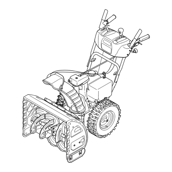
Two-stage snow thrower
Hide thumbs
Also See for 500 Series:
- Operator's manual (48 pages) ,
- Operator's manual (24 pages) ,
- Operator's manual (32 pages)
Table of Contents
Advertisement
Quick Links
Safe Operation Practices • Set-Up • Operation • Maintenance • Service • Troubleshooting • Warranty
OPERATOR'S MANUAL
Two-Stage Snow Thrower — 500 & 600 Series
WARNING
READ AND FOLLOW ALL SAFETY RULES AND INSTRUCTIONS IN THIS MANUAL
BEFORE ATTEMPTING TO OPERATE THIS MACHINE.
FAILURE TO COMPLY WITH THESE INSTRUCTIONS MAY RESULT IN PERSONAL INJURY.
P. O. Box 1386, 97 KENT AVENUE, KITCHENER, ON N2G 4J1
Printed In USA
769-09072
07.17.13
Advertisement
Table of Contents

Subscribe to Our Youtube Channel
Related Manuals for Cub Cadet 500 Series


Summary of Contents for Cub Cadet 500 Series
- Page 1 Safe Operation Practices • Set-Up • Operation • Maintenance • Service • Troubleshooting • Warranty OPERATOR’S MANUAL Two-Stage Snow Thrower — 500 & 600 Series WARNING READ AND FOLLOW ALL SAFETY RULES AND INSTRUCTIONS IN THIS MANUAL BEFORE ATTEMPTING TO OPERATE THIS MACHINE. FAILURE TO COMPLY WITH THESE INSTRUCTIONS MAY RESULT IN PERSONAL INJURY.
-
Page 2: Table Of Contents
Choose from the options below: ◊ Visit our web at www.cubcadet.ca ◊ Locate your nearest dealer from Customer Support: 1-800-668-1238 ◊ Contact Cub Cadet • P.O. Box 1386 • 97 Kent Avenue • Kitchener, Ontario, Canada • N2G 4J1... -
Page 3: Safe Operation Practices
Important Safe Operation Practices WARNING! This symbol points out important safety instructions which, if not followed, could endanger the personal safety and/or property of yourself and others. Read and follow all instructions in this manual before attempting to operate this machine. Failure to comply with these instructions may result in personal injury. - Page 4 Safe Handling of Gasoline Never run an engine indoors or in a poorly ventilated area. Engine exhaust contains carbon monoxide, an odorless To avoid personal injury or property damage use extreme care and deadly gas. in handling gasoline. Gasoline is extremely flammable and the Do not operate machine while under the influence of vapors are explosive.
- Page 5 Clearing a Clogged Discharge Chute According to the Consumer Products Safety Commission (CPSC) and the U.S. Environmental Protection Agency (EPA), Hand contact with the rotating impeller inside the discharge this product has an Average Useful Life of seven (7) years, chute is the most common cause of injury associated with snow or 60 hours of operation.
- Page 6 Safety Symbols This page depicts and describes safety symbols that may appear on this product. Read, understand, and follow all instructions on the machine before attempting to assemble and operate. Symbol Description READ THE OPERATOR’S MANUAL(S) Read, understand, and follow all instructions in the manual(s) before attempting to assemble and operate.
-
Page 7: Assembly & Set-Up
Assembly & Set-Up IMPORTANT: The snow thrower is shipped with oil and WITHOUT GASOLINE. After assembly, refer to separate engine manual for proper fuel and engine oil recommendations. NOTE: Remove all loose parts and any packing material before assembling. NOTE: References to right or left side of the snow thrower are determined from behind the unit in the operating position. NOTE: This Operator’s Manual covers several models, handle panels, lights and chute cranks are some features that may vary by model. - Page 8 • Place chute assembly onto chute base and secure chute control assembly to chute support bracket with clevis pin and cotter pin removed earlier. See Fig. 3-4. Fig. 3-6 Fig. 3-4 • Finish securing chute control assembly to chute support bracket with wing nut and hex screw removed earlier.
- Page 9 Drift Cutters (If Equipped) WARNING: Drift cutters should be used when operating the snow thrower in Never use your hands to clean snow heavy drift conditions. and ice from the chute assembly or auger housing. • On models so equipped, drift cutters and hardware are Lamp Wiring Harness (If equipped)) assembled to the auger housing inverted.
- Page 10 Tire Pressure The tires are over-inflated for shipping purposes. Check the tire pressure before operating the snow thrower. Refer to the tire side wall for tire manufacturer’s recommended psi and deflate (or inflate) the tires as necessary. WARNING: Under any circumstance do not exceed manufacturer’s recommended psi.
- Page 11 Auger Control Test WARNING : Prior to operating your snow thrower, carefully read and follow all instructions below. Perform all adjustments to verify your unit is operating safely and properly. Perform the following test before operating your snow thrower for the first time and at the start of each winter. Check the adjustment of the auger control as follows: When the auger control is released and in the disengaged “up”...
-
Page 12: Controls
Controls and Features 2 Way Chute Control (optional) Drive Control Auger Control Shift Lever Heated Grips (optional) Headlight (optional) Steering Trigger Control (optional) Chute Directional Control Chute Assembly Clean Out Tool Drift Cutters (optional) Skid Shoe Augers Fig. 4-1 Skid Shoes Snow thrower controls and features are described below and illustrated in Fig. - Page 13 Drift Cutters (if so equipped) Steering Trigger Controls (if so equipped) The drift cutters are designed for use in deep snow. Their use is optional for normal snow conditions. Maneuver the snow thrower so that the cutters penetrate a high standing snow drift to assist snow falling into the augers for throwing.
- Page 14 Two-Way Chute Control™ (optional) CHUTE DIRECTIONAL CONTROL This two-way control lever is meant to control the distance of snow discharge from the chute. Tilt the lever forward or rearward to adjust the distance snow will be thrown. Chute Directional Control (optional) DISCHARGE DISCHARGE RIGHT...
-
Page 15: Operation
Operation Starting and Stopping the Engine Replacing Shear Pins Refer to the Engine Operator’s Manual packed with your snow The augers are secured to the spiral shaft with shear pins and thrower for instructions on starting and stopping the engine. bow-tie cotter pins. -
Page 16: Maintenance & Adjustment
Maintenance & Adjustments Maintenance Lubrication Engine Wheels Refer to the Engine Operator’s Manual. At least once a season, remove both wheels. Clean and coat the axles with a multipurpose automotive grease before reinstalling Tire Pressure wheels. Refer to Assembly and Set-up section for information regarding Auger Shaft tire pressure. - Page 17 Adjustments Shift Cable If the full range of speeds (forward and reverse) cannot be achieved, adjust the shift cable as follows: Place the shift lever in the fastest forward speed position. Loosen the hex nut on the shift cable index bracket. See Figure 6-5.
- Page 18 Drive Control Chute Assembly (Overhead Chute Control) When the drive control is released and in the disengaged “up” If the chute fails to remain stationary during operation, the position, the cable should have very little slack. It should NOT be pre-load of the chute can be adjusted by tightening the hex nut tight.
-
Page 19: Service
Service Belt Replacement Carefully pivot the snow thrower up and forward so that it rests on the auger housing. Auger Belt Remove the frame cover from the underside of the snow thrower by removing the self-tapping screws which secure To remove and replace your snow thrower’s auger belt, proceed it. - Page 20 Drive Belt Remove the belt from around the auger pulley, and slip the belt between the support bracket and the auger pulley. NOTE: Special tools are required and several components must See Figure 7-5. be removed in order to replace the snow thrower’s drive belt. See NOTE: Engaging the auger control will ease removal and your authorized service dealer to have the drive belt replaced or reinstallation of the belt.
-
Page 21: Troubleshooting
Troubleshooting Problem Cause Remedy Engine fails to start 1. Choke not in CHOKE position. 1. Move choke to CHOKE position. 2. Spark plug wire disconnected. 2. Connect wire to spark plug. 3. Fuel tank empty or stale fuel. 3. Fill tank with clean, fresh gasoline. 4. -
Page 22: Replacement Parts
Wheel Drive Belt (24”) 954-04195 Auger Drive Belt (26”, 28” & 30”) 954-04201A Wheel Drive Belt (26”, 28” & 30”) 684-04159C Friction Wheel Assembly (500 Series) 684-04153C Friction Wheel Assembly 600 Series) 935-04054 Friction Wheel Rubber (all models) 925-1629 Lamp, 12V 738-04124A Shear Pin, 1.50... -
Page 23: Warranty
THREE YEAR LIMITED WARRANTY The limited warranty set forth below is given by MTD Products Limited with respect to new merchandise purchased and used in Canada and/ or its territories and possessions (either entity respectively, “MTD”). MTD warrants this product (excluding its normal wear parts as described below) against defects in material and workmanship for a period of three (3) years commencing on the date of original purchase and will, at its option, repair or replace, free of charge, any part found to be defective in materials or workmanship. - Page 24 Notes...
Need help?
Do you have a question about the 500 Series and is the answer not in the manual?
Questions and answers