
Subscribe to Our Youtube Channel
Related Manuals for Komshine QX55 Series


Summary of Contents for Komshine QX55 Series
- Page 1 enabling today,inspiring tomorrow QX55-S & QX55-P Master OTDR OTDR · OPM · SLS · VFL · FIP · RJ45...
-
Page 2: Preorder
Limited(Komshine). The contents of this document are subject to change without notice. Information from Komshine is supposed to be true and reliable. Komshine will not take any responsibility for the errors contained in this document or the accidental or secondary losses caused by the supply and use of this document or the practicality of the version of the document. -
Page 3: Safety Terms In This Manual
enabling today,inspiring tomorrow Safety terms in this manual A warning symbol indicates danger. It prompts the user to pay attention to a certain process, an operation method or the like. Failure to operate correctly or follow the rules may cause per- sonal injury. -
Page 4: Matters Need Attention
Matters that need attention Battery: The power supply battery of OTDR of Komshine is rechargeable li-polymer. If you don't use the instrument for a long time, please charge the battery before using it. If the instrument is idle for more than 2 months, you should charge it in time to keep the battery power. -
Page 5: Table Of Contents
enabling today,inspiring tomorrow Content Preorder....................................... Safety instruction ................Safety terms in this manual ....................Warning items ..................Matters need attention I. Overview....................................1. Contents of this manual .............. 2. Unpacking inspection of products .................. 3. Product introduction ................. 4. - Page 6 enabling today,inspiring tomorrow III. Introduction of OTDR functions........................1. Test information of curve interface ..................2. Link map page ..................... 3. Setup page ................4. Wavelength switching ............... 5. PON function introduction Enclosure..................................... A. Event type description ........... Maintenance and calibration instructions ..................
-
Page 7: Overview
enabling today,inspiring tomorrow I. Overview 1. Contents of this manual First of all, thank you for choosing our products. Please read this manual carefully before using it, especially the warning and attention information, so as to avoid injury to your body or instrument due to wrong operation.This manual mainly contains the common oper- ation and maintenance information of the instrument, as well as troubleshooting guide and various information about obtaining technology and service.All the instruments have gone... -
Page 8: Principle Introduction
enabling today,inspiring tomorrow to record the optical fiber transmission quality, it is necessary to measure the optical path, total loss, loss of all joints and connectors.By looking at the "event points" in the optical fiber, the installation and maintenance personnel point out these irregularities in the optical fiber, locate their positions, and measure the attenuation between them, as well as the resulting loss and attenuation uniformity.In a word, OTDR is a necessary tool for the pro- duction, installation and maintenance of optical fiber and optical cable. -
Page 9: Features Of This Product
enabling today,inspiring tomorrow 5. Features of the product: 1) Basic functions of OTDR: a.Measure the length of optical cable and optical fiber; b.Determine the location of optical cable and optical fiber fault point and breakpoint; c.Describe the loss distribution curve of optical cable and optical fiber; d.The attenuation coefficient of optical cable and optical fiber is measured;... - Page 10 enabling today,inspiring tomorrow 2) Other incidental functions: a. VFL function: 650 ± 20nm light source is used for this function, and visual light source is provided for optical fiber fault location by means of visualization, the visible light source emits red light visible to human eyes, which can be detected in the blind area of optical fiber test direct fault (breakpoint) location, and can also be used for core comparison in multi-core opti- cal cable.
- Page 11 enabling today,inspiring tomorrow c. OPM function: This function is used to measure the power of the light source, and supports the measurement of optical power of multiple wavelengths. d. FIP function: This function is used to detect the cutting quality of optical fiber end face and its cleanliness;...
- Page 12 enabling today,inspiring tomorrow e. Flashlight function: This function provides a guarantee for the normal use of the instrument under the condition of insufficient lighting conditions; f. RJ45 function: This function is divided into two functions: line searching and line alignment. The alignment is to test whether the line sequence of the network cable is correct and whether it is accessible;...
-
Page 13: The Basic Operation
This chapter introduces the basic operation methods of the instrument, mainly including the description of the instrument keys and the use of common interfaces of the instrument. If you have any questions during the use, please contact the technical support staff of Komshine or our agent. -
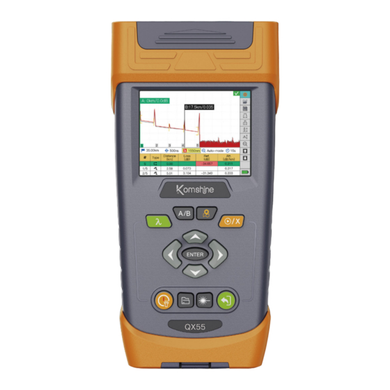
Page 14: Description Of Instrument Keys
enabling today,inspiring tomorrow 2. Description of instrument keys Switch curve interface and A / B benchmarking key link diagram interface Switch wavelength at OTDR Test dual wavelength ENTER key Direction key Power on key ESC key File management 1)Enter the key When testing optical fiber with dual wavelength, two curves will appear on the main interface of OTDR. - Page 15 enabling today,inspiring tomorrow 2) Enter key ENTER It is used to change the setting parameters, select the content of interest, and enable the corre- sponding functions. 3) Power on key The power on key has two functions. Long press the button to realize the function of switch on and off;Press the button briefly to turn the flashlight on or off.Among them, the flashlight func- tion can be turned on and off in each interface.
- Page 16 enabling today,inspiring tomorrow 6) Switch button In OTDR interface, the key is used to switch between link map and test curve;When the current display is the test curve, press this button to display the link map; when the current display is the link map, press this button to display the test curve.
-
Page 17: Battery And Charging
enabling today,inspiring tomorrow 3. Battery charging 1) Electric quantity display When the machine is turned on, we can see the battery information in the upper right corner of the machine: The battery power is ≤5%, which is in a very low state. If the battery is not charged, it will be turned off soon;... -
Page 18: Operate Vfl Function
enabling today,inspiring tomorrow 4. Operating VFL function: This function is easy to use. Control the "up and down" direction keys, hold the cursor at the corresponding position, and then select the mode you want to set according to the prompt infor- mation in the following figure. -
Page 19: Operate Sls Function
enabling today,inspiring tomorrow 6. Operating SLS function: The stable light source (SLS) function and OTDR function share one port. The SLS function supports stable light sources with 1310 and 1550 wavelengths, and the output power is above -10dBm. As shown in the figure below, note that wavelength switching and frequency switching can only be operated when the light source function is turned on;... -
Page 20: Operate Rj45 Functions
enabling today,inspiring tomorrow Among them, the open file button displays the saved optical fiber end face picture; Saving refers to saving the picture of the optical fiber end face currently being tested; Centering refers to placing the fiber end face in the center of the display area. 8. - Page 21 enabling today,inspiring tomorrow Number EIA/TIA568A Number Result:Test complete! 2)Network search function: This function is used to find the target network cable among multi- ple network cables, as shown in the following figure: Common Search Result:Test complete! When using this function, you need to use external equipment network line finder; First, connect one end of the network cable to RJ45 port of the instrument;...
-
Page 22: Document Management
enabling today,inspiring tomorrow 9. Document management Open File File List files by type Path /dataDisk/screenshots New Folder File name Date Rename BMP004.bmp 2022/09/06 Delete BMP003.bmp 2022/09/06 Check all BMP002.bmp 2022/09/06 BMP001.bmp 2022/09/06 Derive Function introduction of each option in file management function Open file Open selected file This option is to display docs by types in the left... - Page 23 enabling today,inspiring tomorrow 1) Opening file This option is to open the selected file on the left side of the interface. 2) Type of files list By setting different options, the corresponding files will be displayed in the left area; For exam- ple, if the sor option is selected, only folders and SOR files will be displayed in the file list on the left.
- Page 24 enabling today,inspiring tomorrow 4) Rename This option is to modify the name of the selected file or folder. Click this option, and a keyboard interface will pop up. The difference is that the name of the original file is displayed at the input of this interface, as shown in the figure below: File Name of original document...
- Page 25 enabling today,inspiring tomorrow 6) Check all In order to manage files in batches, this option is set, that is, all files in the left display area are selected for deletion, export and other operations; When all files are selected, as shown in the figure below, a "√"...
-
Page 26: System Settings
enabling today,inspiring tomorrow 10. System settings Set the main interface of the system as shown in the figure below: Language English Auto power-off Stand-by time KeyWarning Factory default Update System info User guide Self calibration Function introduction of each option in file management function Chinese, English, French, Portuguese, Thai, Russian, Language Korean and Spanish. - Page 27 enabling today,inspiring tomorrow 1) Language Select the language, and press enter to display the interface shown above. Users can set the lan- guage according to their own needs; Use the up and down arrow keys to find the language to be set, and press enter to set it successfully.
- Page 28 enabling today,inspiring tomorrow 3) Standby time The standby time option refers to the automatic screen blanking according to the time set by the user without operating the instrument. This function effectively saves the power consumption of the instrument and prolongs the service life of the instrument. Especially when users use the instrument outdoors, it is inconvenient to charge, which greatly improves the working efficien- cy.
- Page 29 enabling today,inspiring tomorrow OTDR LightSource RJ45 File 6) Restore factory settings During the user's use of the instrument, some parameters of the instrument may be calculated incorrectly or some functions may not be used due to some inadvertent misoperation. At this time, you don't need to worry, just find the option of restoring factory settings in the system settings interface, restore the instrument to its original factory state, and restart the test to get the correct results.
- Page 30 7) Upgrade Komshine instruments will always maintain and upgrade their functions. This option provides customers with an upgraded interface. You only need to put the latest version of the software into the USB device to upgrade. The operation is easy to learn and very convenient. However, in order to prevent the unexpected situation in the process of upgrading, which leads to the fail- ure of upgrading, we have made the battery power limit for software upgrading.
- Page 31 enabling today,inspiring tomorrow 8) System information The contents of the system information options in the following figure store some basic infor- mation of the instrument, including the model of the instrument module, the unique serial number of the instrument, the software version number and the software version date. As shown in the figure below: Language English...
- Page 32 enabling today,inspiring tomorrow a. Circuit self-calibration: the self-calibration function to prevent the instrument test from having problems due to the zero-point drift of the circuit voltage; b. Optical path self-calibration: self-calibration to prevent the deviation of the length of the test optical fiber or optical cable due to the inaccurate position of 0 point of the curve;...
-
Page 33: Introduction Of Otdr Functions
enabling today,inspiring tomorrow III. Introduction of OTDR functions This chapter introduces the basic operation method of OTDR, mainly including the operation method of OTDR, the description of various parameters and the introduction of functions. OTDR Settings open files A: 0km/0.0dB save files B:17.5km/0.035 Horizontal magnifying curve... -
Page 34: Test Information Of Curve Interface
enabling today,inspiring tomorrow 1. Test information of the interface The curve interface mainly analyzes the relevant information of the curve, as shown in the figure: Horizontal and vertical coordinate information Pass and Fail Status Tag line information A: 0km/0.0dB B:17.5km/0.035 B: 24.094 Test curve Measuring conditions... - Page 35 enabling today,inspiring tomorrow A: 0km/0.0dB B:17.5km/0.035 B: 24.094 1000.00m 50ns 1310nm Auto-mode Distance Loss Ref. Att. Type (km) (dB) (dB) (dB/km) -38.480 0.464 0.00 217.70 0.289 -41.709 0.335 327.97 0.783 -50.788 0.327 2)Test information: As shown in the figure below on the left, the red box is the test condition of the current curve: measuring range: 1000m;...
- Page 36 enabling today,inspiring tomorrow 3)Curve operation: In order to facilitate users to view the details of the curve, in this interface, you can use the options on the right side of the curve to zoom in and out of the curve; Note that the reference point of zoom-in and zoom-out is the intersection of the curve and the selected mark line.
- Page 37 enabling today,inspiring tomorrow 4)Event list: The event list page is mainly for users to view the detailed information of all events in the whole optical fiber link, as shown below: A: 0km/0.0dB B:17.5km/0.035 B: 24.094 1000.00m 50ns 1310nm Average Distance Loss Ref.
- Page 38 enabling today,inspiring tomorrow b. Type: The types of events are: group events, reflection events, non-reflection events, gain events, echo (ghost) events, start events, end events, analysis end events, continuous fiber events, etc. The significance of each event type, as shown in the figure below; c.
- Page 39 enabling today,inspiring tomorrow 5)Pass and fail: In the red box shown in the figure below, whether the measurement result is passed is judged according to the set threshold; These thresholds include reflectivity, loss, attenuation and other threshold settings; When the test result is greater than the set threshold, the background will be set to red in the event list;...
- Page 40 enabling today,inspiring tomorrow Open file: the file in the list can be opened by clicking the enter key, and the OTDR test curve corresponding to the current file will be displayed on the OTDR main interface. A: 2.556 Open the file A: 2.556 B: 24.094 Path...
-
Page 41: Link Map Page
enabling today,inspiring tomorrow 2. Link map page On the OTDR curve interface, press according to the optical fiber link representation to switch to the link map page. On this interface, the sequence of events is displayed from left to right. As shown in the figure below: Move left Selected event Move right... -
Page 42: Setup Page
enabling today,inspiring tomorrow h. You can also switch events through the option. At this time, the events in the link map will also change. The operation mode of event switching is the same as the curve interface. i. The meaning of the event icon in this interface is shown in the following figure: Icon Event Type Instruction Initial point The start of the measured fiber... - Page 43 enabling today,inspiring tomorrow 1)Test settings For novices, or when they don't know the situation of optical fiber links, it is recommended to use Auto mode for testing. The instrument will intelligently set the optimal test conditions according to the actual situation of optical fiber links. If you want to conduct a special test, you can manually set the measurement conditions you want;...
- Page 44 enabling today,inspiring tomorrow Real-time mode is used for real-time monitoring of links; At this time, the application program refreshes the measurement curve in real time without averaging, and the refresh frequency is 2~5Hz; Note that the real-time mode only supports one wavelength test. In real-time mode, the test duration is not displayed, and only two characters "RT"...
- Page 45 enabling today,inspiring tomorrow b.Measuring range Is the length set by the user when OTDR tests the optical fiber; The required range is greater than 20% of the actual length of the optical fiber; Because the measuring range and resolution are closely related, the measuring range should not be too large when testing. It is recommend- ed that the measuring range be within the range of 1.5~2.0 times of the length of the optical fiber.
- Page 46 enabling today,inspiring tomorrow c. Pulse width That is, the pulse width OTDR test is the pulse width of the emitted light; This parameter directly determines our measurement. Test results (signal-to-noise ratio, event resolution, etc.); Selecting narrow pulse width test can achieve higher range resolution and smaller blind area, but the signal-to-noise ratio of the curve will inevitably be damaged;...
- Page 47 enabling today,inspiring tomorrow auto pulse(ns) Note: If the pulse width is set by Auto, the actual pulse width may be different from the above table. This is because the automatic setting of pulse width is not only constrained by the range, but also affected by the actual fiber length and wavelength.
- Page 48 enabling today,inspiring tomorrow As shown in the figure above, at present, the instrument supports six test time settings: Auto, 15s, 30s, 60s, 90s, 120s, 180s, and L, of which auto defaults to 15s. e. Distance unit Different countries and regions have different commonly used length units. In order to meet the needs of most customers, the distance units supported by this instrument are: M, KM, FT, KFT and MILE.
- Page 49 enabling today,inspiring tomorrow f. Wavelengths The light used in OTDR is usually used for communication; It is used for single-mode fiber, and the wavelengths are 1310nm,1490nm and 1550nm. There are also light with wavelengths of 1300nm and 850nm for multimode fiber; There are also lights with wavelengths of 1625nm and 1650nm for online monitoring.
- Page 50 enabling today,inspiring tomorrow A: 0km/0.0dB B:17.5km/0.035 B: 24.094 1000.00m 50ns 1550nm Average 15 s Distance Loss Ref. Att. Type (km) (dB) (dB) (dB/km) 0.00 -37.942 0.180 217.69 0.352 -42.592 0.180 327.95 0.643 -51.807 0.180 Note: The macro-bending event will only appear during the dual-wavelength test, so you must use the dual-wavelength test if you want to test the macro-bending event.
- Page 51 enabling today,inspiring tomorrow a. Refractive index Refractive index, also known as group coefficient, is used to convert light propagation time into distance. For all OTDR measurements related to distance, such as event location, attenua- tion, segment length, total length, etc., the correct refractive index is crucial. Provided by opti- cal cable manufacturer or optical fiber manufacturer.
- Page 52 enabling today,inspiring tomorrow b. Backscattering coefficient The backscattering coefficient used by this OTDR refers to the amount of Rayleigh backscat- tered light of a specific optical fiber. This parameter will affect the calculation results of return loss and reflectivity, and is generally provided by optical cable manufacturers. This parameter is also related to the wavelength.
- Page 53 enabling today,inspiring tomorrow A: 2.556 Analysis Parameter A: 2.556 B: 24.094 Refractive index 1.467700 B: 24.094 -79.44 Back scattering 10.000 Helix factor Default Lanuch and Receive Fiber Fiber Length Fiber Event 0.00m Launch Fiber Length 实时 640ns 60km 5.00m Receive Fiber Length 距离...
- Page 54 enabling today,inspiring tomorrow When injecting optical fiber is used for OTDR testing, a section of optical fiber is injected into the interface of the instrument, and then the tested optical fiber is connected; The receiving optical fiber is a section of optical fiber connected to the end of the tested optical fiber. The injection fiber and the receiving fiber can be set separately.
- Page 55 enabling today,inspiring tomorrow When setting the receiving fiber according to the fiber length, the operation logic is the same as setting the injection fiber, and it will be set at the appropriate position as the end point of the span. As shown in the figure below: A: 2.556 Analysis Parameter A: 0km/0.0dB...
- Page 56 enabling today,inspiring tomorrow Note: After the injection fiber is set, the positions of the incident points before the start of the span are all negative, and the start of the span is at 0 o'clock. Setting threshold In the threshold setting interface, you can set your criteria for judging optical fiber links. Among them, the option of "curve passing threshold setting"...
- Page 57 enabling today,inspiring tomorrow Curve through threshold setting a. Splicing loss The joint loss threshold is the threshold for judging the state of small non-reflection events; General welding events, bending, Curved event loss is relatively small, so this threshold setting is small; If the loss of non-reflective events is found to exceed. If the threshold is exceeded, it is generally considered that the welding is not good, or the bending radian is large, so mainte- nance is needed;...
- Page 58 enabling today,inspiring tomorrow Set the analysis threshold a. Welding loss Setting the analysis threshold can help users eliminate some known ones with small measure- ment loss events; Of course, in order to comprehensively analyze the events on the optical fiber link, the threshold can also be set to a small value, At this point, all events can be displayed in the event list.
- Page 59 enabling today,inspiring tomorrow b. Optical fiber end loss The fiber end loss threshold is used to stop the analysis immediately when serious event loss occurs (for example, the location where the event that may endanger the network signal trans- mission occurs). When the event loss in the optical fiber link is greater than the set end thresh- old, the event will be set as the end, and the event information after the event will not be displayed.
- Page 60 enabling today,inspiring tomorrow Report settings In the report setting interface, the content in the PDF report is mainly set when the PDF report is generated. The main settings are as shown in the figure below: A: 2.556 Report Setting A: 2.556 B: 24.094 Cable ID B: 24.094...
- Page 61 enabling today,inspiring tomorrow b. Press the left arrow key to move the cursor to the left side of the display interface and enter the target folder; As shown in the figure below: Default Folder Path /dataDisk File name Date c. Press the right arrow key to move the cursor to the right side of the display interface and stay at the icon;...
-
Page 62: Wavelength Switching
enabling today,inspiring tomorrow 4. Wavelength switching When using dual-wavelength test fiber, two curves will appear on OTDR main interface. At this time, the curves are switched by key, as shown in the following figure, the images before and after waveform switching. The red curve is the current curve and the gray curve is the curve to be analyzed. - Page 63 enabling today,inspiring tomorrow In the setting interface of OTDR, in the test setting, there is an additional SM Live option in the wavelength setting option. When this option is selected, the wavelength is switched to 1625nm, as shown in the following figure: A: 2.556 Measurement Setting A: 2.556...
-
Page 64: Enclosure
enabling today,inspiring tomorrow Annex A. Event type description This section describes all possible event types in the event table generated by the application. Different event types are represented by different symbols. Start event The "start event" on the curve is the event that marks the beginning of the fiber span. By default, the "Start Event"... - Page 65 enabling today,inspiring tomorrow End of analysis event Continuous Fiber Event This event indicates that the selected data acquisition range is shorter than the optical fiber. Since the analysis process was finished before the end of the fiber, the end of the fiber was not detected.
- Page 66 enabling today,inspiring tomorrow Non-reflective event This kind of event is characterized by the sudden decrease of Rayleigh backscattering signal level, which shows the discontinuous slope of curve signal. Such events are usually caused by splices, macro bends or micro bends in optical fibers. The application will display the loss value of non-reflective events, but not the reflectivity.
- Page 67 enabling today,inspiring tomorrow The reflection event The reflection event appears as a spike in the fiber curve. They are caused by a sudden change in refractive index. The reflection event will cause most of the energy initially injected into the fiber to be reflected back to the light source.
- Page 68 enabling today,inspiring tomorrow Echo event It indicates the false reflection event caused by multiple reflections of the echo at the end face of the optical fiber. Echo events are usually called ghost events. The distance between the echo event and the front end face is equal to the distance between the two end faces forming the echo.
-
Page 69: Maintenance And Calibration Instructions
enabling today,inspiring tomorrow B. Maintenance and calibration instructions 1. Maintenance of battery The battery used in this instrument is a polymer lithium rechargeable battery: The following points should be paid attention to in battery maintenance: It's best to store the instrument (including battery) at room temperature (15℃ to 30℃) and place it in a dry place to get the best performance. -
Page 70: Warranty Terms
enabling today,inspiring tomorrow C. Warranty terms 1. Warranty policy 1) Free warranty will be implemented within 3 years from the date of delivery. 2) Standard fittings or wearing parts, if there are material or process problems, will be guaran- teed free of charge within 1 year from the date of delivery. 3) If it is confirmed that there is a problem with the product during the warranty period, it will be responsible for the domestic transportation of the product. - Page 71 As mentioned above, the buyer acknowledges that Komshine is the only exclusive after-sales service organi- zation, providing service for repairing or replacing defective parts. The Buyer confirms that...
-
Page 72: Technical Index Information Of Otdr
enabling today,inspiring tomorrow D. Technical index information of OTDR OTDR Specifications Model QX55-S QX55-P PON 1310/1550/1625 Wavelength (nm) 1310/1550 (built-in filter) Dynamic range (dB) 32/30 32/30/28 Number of optical port Applicable fiber SM (ITU-T G.652) Distance range (km) 0.5,1,2,5,10,20,35,50,75,100,150,200 Pulse width (ns) 5,10,20,50,100,200,500,1000,2000,10000,20000 Event dead zone*1 (m)
Need help?
Do you have a question about the QX55 Series and is the answer not in the manual?
Questions and answers