Table of Contents
Advertisement
Quick Links
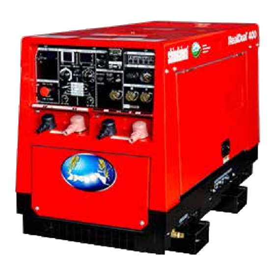
OWNER'S AND OPERATOR'S MANUAL
DGW400DML
Vertical, Water-Cooled 4-Cycle Diesel Engine
WARNING
Breathing diesel engine exhaust exposes you to chemicals known to the State of
California to cause cancer and birth defects or other reproductive harm.
Always start and operate the engine in a well ventilated area.
If in an enclosed area, vent the exhaust to the outside.
Do not modify or tamper with the exhaust system.
Do not idle the engine except as necessary.
For more information go to www.P65warnings.ca.gov/diesel.
WARNING
Cancer and reproductive Harm-
www.P65Warnings.ca.gov
WARNING
Batteries, battery posts, terminals and related accessories contain lead and lead
compounds, and other chemicals known to the State of California to cause
cancer and birth defects or other reproductive harm. WASH HANDS AFTER
HANDLING.
CAUTION
Do not operate the Generator/Welder, or any other appliance, before you have read
and understood the instructions for use and keep near for ready use.
California Proposition 65
DGW400DML-D2V
X753-008 19 0
X753803-330 5
Advertisement
Table of Contents

Subscribe to Our Youtube Channel
Related Manuals for Shindaiwa DGW400DML


Summary of Contents for Shindaiwa DGW400DML
- Page 1 OWNER’S AND OPERATOR’S MANUAL DGW400DML Vertical, Water-Cooled 4-Cycle Diesel Engine California Proposition 65 WARNING Breathing diesel engine exhaust exposes you to chemicals known to the State of California to cause cancer and birth defects or other reproductive harm. Always start and operate the engine in a well ventilated area.
- Page 3 Introduction We would like to thank you very much for purchasing this Shindaiwa Soundproof Diesel Engine Generator & Welder. This manual has been created in order to ensure safe and proper use of this equipment. Be sure to thoroughly read this manual before operating the equipment as the improper operation of this equipment can result in an accident or malfunction.
-
Page 4: Table Of Contents
Table of Contents 1. Safety Precautions ..................2 2. Specificaons ....................6 3. Applications ....................7 4. Part Names ....................7 5. Equipment ....................10 5-1. Spill Containment ................. 10 5-2. Idle Control ................... 10 5-3. Weld Output Control ................11 5-4. -
Page 5: Safety Precautions
1. Safety Precautions Danger: Using a generator indoors CAN KILL YOU MINUTES Generator exhaust contains carbon monoxide. This is a poison you cannot see or smell. NEVER use inside a home or garage, EVEN IF doors and windows are open. ... - Page 6 Warning: Fire Keep any ignitable items (such as fuel, gas and paint) or inflammable items away from the equipment because the muffler, exhaust fume and other parts attain high temperatures. Keep any ignitable items (such as fuel, gas and paint) or inflammable items away from the work area due to the scattering of weld spatter that occurs during welding.
- Page 7 Caution: Burn The engine, muffler and similar parts are extremely hot during operation and immediately after stopping the equipment. Never touch hot parts. Never open the radiator cap during operation or immediately after stopping the equipment. Hot cooling water and steam will spurt out. ...
- Page 8 Location of Danger/Warning/Caution Labels Replace danger, warning or caution labels when they become difficult to see or damaged by affixing new labels in the specified locations. Order the necessary labels by numbers in parentheses. ⑴ Suffocation from Exhaust Fume (No. X505-007590) ⑵...
-
Page 9: Specificaons
2. Specificaons Model DGW400DML-D2V Generating Method Rotating Field Operation Single Dual Rated Current (A) Rated Voltage (V) 35.2 28.0 Duty Cycle Current Adj. Range (A) 30 – 390 30 – 210 DROOP Welding Rod (in.) 5/64 – 5/16 5/64 – 5/32 Gouging Rod (in.) -
Page 10: Applications
3. Applications Shielded Metal Arc Welding Semi-automatic Arc Welding (MIG, MAG, Self-Shielded) Gouging Lift Start TIG, Scratch Start TIG Power Source for Light, Electric Tools and Appliances Caution: Physical and Secondary Damage Do not use the equipment for any applications not listed above. Improper usage can result in an accident or malfunction. - Page 11 3-P 240V Receptacle (Inside) 1-P 120/240V Breaker 1-P 120/240V Receptacle VRD Switch Main Breaker Bonnet Grounding Terminal Ground Fault Circuit Interrupter 1-P 120V Breaker Forklift Skid (GFCI) Receptacle Right Door Air Cleaner Fuel Lever (Fuel Strainer) Oil Plug Oil Inlet Sub Tank Fuse Oil Gauge...
- Page 12 Fuel Inlet Cover Fuel Inlet Lifting Lug Muffler Top Plate Accessories Owner’s and Product Engine Operator’s Warranty Warranty Manual Manual Manual Terminal Cap Terminal Cap Tail Pipe Pipe Band (Black/For [ (Red/For [ + ]) 1 part 1 part 2 parts 2 parts - 9 -...
-
Page 13: Equipment
5. Equipment 5-1. Spill Containment Warning: Fire Always be sure to wipe up any spilled fuel or oil. Spilled fuel and oil accumulates in the spill containment. Do not operate the equipment with liquid accumulated in the spill containment. ... -
Page 14: Weld Output Control
(2) Auto Idle The equipment includes an auto idle function in order to reduce noise, save fuel, and reduce exhaust gas emission. You can set the idle control switch to "AUTO" so that the engine operates at low speed when not welding or using the equipment as a power source. When you start to weld or use as an AC power source, the engine automatically increases to high speed. -
Page 15: Remote Control (9-Pin Connector)
If the weld mode selector is set to "DROOP-STICK", "GOUGING", "LIFT START TIG" or "CC-STICK", you can pre-set the output current using the output control dial. (3) Arc Control (for CC-STICK mode) The equipment includes an arc control function that adjusts the Weaker Stronger arc strength. -
Page 16: Error Code Display
(2) AC Meter The equipment includes an AC meter that displays the three AC Meter phase 240V generated output. The AC meter is equipped with an AC meter selector that can be switched to display voltage, current or frequency. <Note> ... -
Page 17: Ground Fault Circuit Interrupter (Gfci) And Grounding
(1) Water Temperature Monitor Lamp The water temperature monitor lamp ("WATER TEMP") lights up and the engine is automatically stopped if the cooling water temperature becomes irregularly high during operation. If this occurs, inspect the water level of the sub tank and add cooling water if the water level is insufficient. -
Page 18: Emergency Stop Switch (Option)
<Note> The GFCI receptacles are protected by the ground fault circuit interrupters. (1) Operation Check of Ground Fault Circuit Interrupters Be sure to always check the ground fault circuit interrupters before starting operation according to the following procedures. Idle Control 1) Start the engine. -
Page 19: Vrd (Voltage Reduction Device)
5-10. VRD (Voltage Reduction Device) The equipment includes a voltage reduction device on the Left weld output side. The voltage reduction device reduces the Door output voltage of the welder when welding is paused in order to further increase safety when welding in locations with high humidity, elevated locations, extremely confined spaces near possible hazards, and similar conditions. -
Page 20: Transporting
<Note> The wire feeder control function is only for output A. When the circuit protector for the wire feeder operates due to an overcurrent fault, inspect for the fault and press the circuit protector button after resolving the fault in order to reset the system. -
Page 21: Pre-Operation Inspection
7. Pre-Operation Inspection Warning: Injury/Electric Shock Do not operate the equipment with any doors or covers open. There is a danger of hair, body parts and other items being caught up in moving parts such as cooling fans and belts. -
Page 22: Cooling Water Inspection
7-2. Cooling Water Inspection Caution: Burn Never open the radiator cap during operation or immediately after stopping the equipment. Hot cooling water and steam will spurt out. Check that the sub tank cooling water level is within the range of "FULL" and "LOW". If the cooling water level is lower than "LOW", add water to both the sub tank and radiator. -
Page 23: Spill Containment Inspection
<Note> Do not use any fuel other than the specified light oil type. Doing so may lead to the problems described below. This machine complies with the exhaust gas regulations. If you use any type of fuel other than the specified light oil type, the machine will be a product not conforming to the exhaust gas regulations. -
Page 24: Operating Procedures
Warning: Explosion Do not operate the equipment or recharge the battery when the battery fluid level is below the lower level. Do not generate any sparks near the battery and do not allow any fire or other open flame near the equipment because the battery generates ignitable gas. -
Page 25: Starting The Engine
Caution: Injury Use this equipment with it situated on a stable level surface so that it is prevented from moving. Do not move the equipment during operation. Always be sure to turn off the switches of all devices using the equipment and turn off the equipment breakers before starting the engine. -
Page 26: Stopping The Engine
Restarting after Stopping due to Running Out of Fuel The equipment includes an automatic air-bleeding device. You can easily restart the engine according to the following procedures even if the engine stops due to running out of fuel. 1) Turn all breakers (Main, 1-P 120/240V and 1-P 120V) to "OFF". 2) Turn the RUN/STOP switch to the "STOP"... -
Page 27: Using As A Welder
9. Using as a Welder 9-1. Welding Cable Selection Use welding cables with a cross-sectional area that is larger than the proper cross- sectional areas indicated in the table below. Using cable that is less than the proper cross-sectional area reduces the weld output. <Note>... -
Page 28: Welding Cable Connection
(2) Semi-automatic Arc Welding (MIG, MAG, Self-shielded) Wire Polarity Applications Connecting Method Indication + (positive) terminal : Earth (Base material) Straight DC– Self-shielded Arc Welding Polarity - (negative) terminal : Torch (wire) + (positive) terminal MIG Welding , MAG Welding :Torch (wire) Reverse Polarity... -
Page 29: Duty Cycle
<Note> Securely crimp the crimped terminals and securely connect the welding cables. Using insufficiently crimped terminals or loosely connected cables can result in heat generation from poor connection, thereby causing burnout of the weld output terminals. Also do not use iron washers, etc., as it may cause heat generation. - Page 30 Caution: Electric Shock If wearing gloves, be sure to always wear gloves with dry insulation properties. Do not wear gloves that are damaged or wet. You can select from among five weld modes in accordance with the type of welding being performed.
- Page 31 Semi-automatic Arc Welding Not Using a Remote Controller Not Using a 14-Pin Connector Output Control Dial 1) Set the weld mode selector to "CV-WIRE". Equipment 2) Switch the single/dual selector in accordance Work Clip Lead with the amount of welding personnel and Wire desired weld output.
-
Page 32: Using As A Generator
10. Using as a Generator 10-1. Output Types and Ranges 1-P 120/240V 3-P 240V (1) 3-Phase 240V Receptacle Receptacle The equipment includes one 3-phase 240V receptacle. The total maximum output available from the receptacle is 15kVA. (2) 1-Phase 120/240V The equipment includes one 1-phase 120/240V receptacle. -
Page 33: Operation
<Note> This equipment is a 60Hz dedicated unit. Use 60Hz devices with this equipment. Devices using a motor might require power that is larger than the device rating. In such cases, consult with the retail outlet where the equipment was purchased. ... -
Page 34: Simultaneously Welding And Using As Ac Power Source
Recovery from Overcurrent Breaker Operation Caution: Injury Always be sure to turn off the power switches of all devices using the equipment when turning on the equipment breakers. Leaving on the power switch of a device using the equipment when the equipment breakers are turned on could result in the sudden operation of the corresponding device. -
Page 35: Inspection/Maintenance
12. Inspection/Maintenance California Proposition 65 WARNING Batteries, battery posts, terminals and related accessories contain lead and lead compounds, and other chemicals known to the State of California to cause cancer and birth defects or other reproductive harm. WASH HANDS AFTER HANDLING. - Page 36 <Note> Procedures except for pre-operation inspection must be performed by specialized technicians. Items indicated by : Contact the retail outlet where the equipment was purchased. Always be sure to use genuine parts when replacing parts. When removing waste liquid from the equipment, place some container to collect the liquid and prevent it from spilling on the ground.
- Page 37 Inspection Period Pre- Every Every Inspection Item Operation 50th Every Every Every 1,000 2,000 Inspection hour 100 hours 200 hours 400 hours hours hours Clean Radiator Fin (External) Clean Radiator (Internal) Inspect/Replace Fuel/Cooling Water/Oil Hoses, Anti-Vibration 1 year Rubber and Packing in Top 2 years...
- Page 38 <Note> Contact the retail outlet where the equipment was purchased if you do not have a filter wrench. Oil filter part no. : 1J090-32430 (Kubota part no.) After adding engine oil, operate the engine for a short period and check that there is no oil leakage.
- Page 39 <Note> Replace the packing with a new part each time you drain the water. Packing part no. : 6C090-58961 (Kubota part no.) Always be sure to check that there is no fuel leakage after tightening the fuel drain plug. (6) Changing the Cooling Water Change Every 2,000 hours or 1 year...
- Page 40 <Note> Secure the drain valve body using a spanner or similar tool so that it does not loosen when removing/installing the plug by turning it. It is possible that there is a fuel or oil leak if the drained fluid contains oily components. If this occurs, check for leakage locations.
-
Page 41: Long-Term Storage
(9) Inspecting/Replacing the Fuel/Cooling Water/Oil Hoses, Anti-Vibration Rubber and Packing in Top and Bottom of Fuel Tank. Inspect Every 400 hours or 1 year Replacement Every 2,000 hours or 2 year If rubber hoses (fuel, cooling water, oil, air, drain, etc.) are hardened or deteriorated, please replace with a new rubber hose. -
Page 42: Troubleshooting
14. Troubleshooting Warning: Electric Shock/Injury Always be sure to stop the engine before performing any equipment check or maintenance. Do not touch the equipment during operation if the equipment or your body is wet. Do not operate the equipment with any doors or covers open. There is a danger of hair, body parts and other items being caught up in moving parts such as cooling fans and belts. - Page 43 Symptom Possible Causes Remedy Starter motor does 1. Battery has a low charge. 1. Recharge the battery. not start. 2. Battery is deteriorated. 2. Replace the battery. 1. Fuel lever is "CLOSE". 1. Turn the fuel lever to "OPEN". 2. Emergency stop switch is "ON". 2.
- Page 44 Symptom Possible Causes Remedy 1. VRD switch is set to "OFF". 1. Set to "ON". VRD does not work. 2. "CV-WIRE" weld mode has been 2. Set to "DROOP-STICK", "GOUGING", selected. LIFT START TIG" or "CC-STICK". Error Code Display Error Code Display Error codes are displayed on the DC and AC meters when the control board detects an error.
-
Page 45: Engine Wiring Diagram
15. Engine Wiring Diagram - 42 -... -
Page 46: Generator Wiring Diagram
16. Generator Wiring Diagram P (1 / 3) - 43 -... - Page 47 P (2 / 3) - 44 -...
- Page 48 P (3 / 3) - 45 -...
- Page 49 - 46 -...
- Page 50 2021 - 47 -...
Need help?
Do you have a question about the DGW400DML and is the answer not in the manual?
Questions and answers