Table of Contents
Advertisement
Quick Links
Original instructions
OWNER'S AND OPERATOR'S MANUAL
DGW 300MS / UK V
Vertical, Water-Cooled 4-Cycle Diesel Engine
CAUTION
Do not operate the Generator/Welder, or any other appliance, before you have
read and understood the instructions for use and keep near for ready use.
DGW300MS/UKV
X753-008 73 0
X753803-440 0
Advertisement
Table of Contents

Related Manuals for Shindaiwa DGW300MS/UKV


Summary of Contents for Shindaiwa DGW300MS/UKV
- Page 1 DGW 300MS / UK V Vertical, Water-Cooled 4-Cycle Diesel Engine CAUTION Do not operate the Generator/Welder, or any other appliance, before you have read and understood the instructions for use and keep near for ready use. DGW300MS/UKV X753-008 73 0 X753803-440 0...
- Page 3 Introduction Thank you for purchasing a Shindaiwa Sound Proof Diesel Engine Generator & Welder. This Operator’s manual has been created to ensure the safe operation of this equipment. Therefore, the manufacturer of this equipment strongly recommends that the user follow the instructions herein, to avoid unnecessary accidents and repairs.
- Page 4 Symbol form / shape Symbol description / application Do not use for Indoor wiring. Do not use in the rain. Beware of eyes and skin. Beware of hot surface. Beware of burn. Beware of injury. Always lock the doors and never open during operation to avoid injury by moving parts.
- Page 5 Ohme, Tokyo 198-8760 JAPAN declares, under the sole responsibility thereof, that the hereunder specified new unit: SOUND PROOF DIESEL ENGINE GENERATOR/WELDER Brand: Shindaiwa Type: DGW300MS/UKV Serial Number W00355005442 toW00355S99999 complies with: ・ the requirements of Directive 2006/42/EC (use of harmonized standard EN 60974-1:2012) ・...
-
Page 6: Table Of Contents
Table of Contents 1. Safety Precautions ..................2 2. Specifications ....................8 3. Applications ....................9 4. Parts Names ....................9 5. Equipment ....................12 5-1. Idle Control ................... 12 5-2. Display ....................12 5-3. Monitor Lamp ..................13 5-4. Earth Leakage Circuit Breaker and Grounding ........14 5-5. -
Page 7: Safety Precautions
1. Safety Precautions Warning: Suffocation from Exhaust Fume Do not operate the equipment in a poorly-ventilated area such as indoors or within a tunnel because the engine exhaust fume includes components that are harmful to humans. Warning: Suffocation from Welding Fume ... - Page 8 Warning: Injury Do not operate the equipment with any doors or covers open. There is a danger of hair, body parts and other items being caught up in moving parts such as cooling fans and belts. Do not modify the equipment and do not operate with parts removed. ...
- Page 9 Caution: Burn The engine, muffler and similar parts are extremely hot during operation and immediately after stopping the equipment. Never touch hot parts. Never open the radiator cap during operation or immediately after stopping the equipment. Hot cooling water and steam will spurt out. ...
- Page 10 ■Location of Warning Labels Replace warning labels when they become difficult to see or damaged by affixing new labels in the specified locations. Order the necessary labels by numbers in parentheses. ① Suffocation from exhaust fumes (No. X505-011481) ② Electric shock (No. X505-011470) ③...
- Page 11 LABEL REPRODUCTION ① X505-011481 ② X505-011470 ③ X564-000640 ④ X564-000630 ⑤ X505-006410 - 6 -...
- Page 12 ⑥ X505-000240 ⑦ X505-004890 ⑧ X505-011490 ⑨ X505-006430 ⑩ M707-000260 ⑪ M708-000890 - 7 -...
-
Page 13: Specifications
2. Specifications Model DGW300MS/UKV Generating Method Rotating Field Rated Current (A) Rated Voltage (V) 32.0 31.2 30.2 27.2 Duty Cycle Current Adj. Range (A) 30 – 200 Welding Rod (φ) 2.0 – 5.0 Current Adj. Range (A) 40 – 300... -
Page 14: Applications
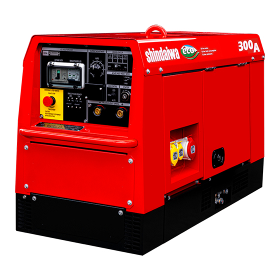
<Note> This CO measurement results from testing over a fixed test cycle under laboratory conditions a parent engine representative of the engine family and shall not imply or express any guarantee of the performance of a particular engine. 3. Applications ... - Page 15 Welding Monitor Lamp Fuel Meter Current Dial 1-P ELCB Display 3-P ELCB (415V Breaker) Display Select Switch Starter Switch 110V Breaker Idle Control Switch Emergency Stop Switch Side Door 1-P 110V Receptacle Air Cleaner Oil Gauge Sub Tank Fuel Lever (Fuel Strainer) Oil Plug Oil Inlet...
- Page 16 Fixed Side Panel Removed Oil Filter Fuel Inlet Muffler Lifting Lug Positioning Handle Positioning Handle Top Plate (Not to be used for lifting) (Not to be used for lifting) Accessories Owner’s and Operator’s Tool Manual Starter Key Door Key 1 Set 1 Set - 11 -...
-
Page 17: Equipment
5. Equipment 5-1. Idle Control The equipment includes an idle control function. Idle Control You can use the idle control switch to select an Switch engine speed setting of "ECO", "AUTO" or "HIGH". (1) ECO Drive The equipment includes an eco drive function in order to reduce noise, save fuel, and reduce exhaust gas emission. -
Page 18: Monitor Lamp
5-3. Monitor Lamp Warning: Injury/Electric Shock Do not operate the equipment with any doors or covers open. There is a danger of hair, body parts and other items being caught up in moving parts such as cooling fans and belts. Caution: Burn ... -
Page 19: Earth Leakage Circuit Breaker And Grounding
5-4. Earth Leakage Circuit Breaker and Grounding Warning: Electric Shock Always be sure to repair the fault when the earth leakage circuit breaker operates. Warning: Fire Do not ground wiring of earth leakage circuit breakers of the equipment to piping that contains through flammable material. -
Page 20: Emergency Stop Switch
(3) If an Earth Leakage Circuit Breaker Operates Caution: Electric Shock/Injury Always be sure to turn off the power switches of all devices using the equipment when turning on the equipment circuit breakers after an earth leakage circuit breaker operates. Leaving on the power switch of a device using the equipment when the equipment circuit breakers are turned on could result in the sudden operation of the corresponding device. -
Page 21: Transporting
6. Transporting Warning: Injury The lifting lug is designed to be used only for lifting the equipment. Do not lift the equipment with any heavy items (such as a trailer, gas canister and additional fuel tank) added to the equipment. Caution: Injury ... -
Page 22: Engine Oil Inspection
Caution: Damage to the equipment or other properties Do not use anything other than the specified optional device because they may cause malfunctions. 7-1. Engine Oil Inspection Caution: Burn Always be sure to stop the engine and allow it to cool before inspecting or changing the engine oil. -
Page 23: Fuel Inspection
(2) Adding Water to the Radiator 1) Open the top plate. 2) Remove the radiator cap. FULL 3) Pour cooling water into the radiator through the inlet port until it reaches the mouth of the port. Sub Tank 4) Tighten the radiator cap. 5) Close the top plate. -
Page 24: Inspection For Fuel/Oil/Cooling Water Leakage
7-4. Inspection for Fuel/Oil/Cooling Water Leakage Warning: Fire Absolutely never use the equipment if there is a fuel, oil or cooling water leak, and be sure to always repair the leak before using. Open the side door and check for fuel leakage from fuel line joints and similar components, and check for oil and cooling water leakage. -
Page 25: Operating Procedures
8. Operating Procedures 1. Warning: Suffocation from Exhaust Fume Do not operate the equipment in a poorly-ventilated area such as indoors or within a tunnel because the engine exhaust fume includes components that are harmful to humans. Warning: Fire ... -
Page 26: Stopping The Engine
Preheat Lamp 3-P 415V Breaker Idle Control Switch 1-P 110V Breaker Emergency Starter Switch Stop Switch <Note> Do not crank the starter motor for 15 seconds or more continuously. If repeating starter switch operation, wait 30 seconds or more between operations. ... -
Page 27: Emergency Stop
8-3. Emergency Stop The equipment includes an emergency stop device. Press the emergency stop switch if you want to immediately stop the engine when an emergency occurs in the work area, the equipment suffers an operating fault, and similar circumstances. <Note>... -
Page 28: Welding Cable Connection
9-3. Welding Cable Connection Warning: Electric Shock Always examine welding cables, power cables and plugs etc., to ensure there are no defects present, prior to operation. Before connecting or disconnecting a welding cable from welding output terminals, stop the engine, and remove the engine key. The person performing this task must always keep the key. -
Page 29: Using As A Generator
Caution: Burn Always be sure to wear leather gloves, apron, shoe covers, arc-proof glasses (face shield), safety shoes, hard hat and long-sleeve clothing to protect against the scattering of weld spatter that occurs during welding. Caution: Injury to Eyes and Skin ... -
Page 30: Usable Device Capacities
10-2. Usable Device Capacities Usable capacity varies depending on the type and performance of the electrical tool or household appliance being used. Overview of Usable Device Capacities Standard Capacities (Units : kW) 1-Phase 110 V 3-Phase 415 V Device Used Total Capacity Receptacle... -
Page 31: Simultaneously Welding And Using As Ac Power Source
1) Turn off the switches of devices being used. 2) Turn all breakers (1-P 110V and 3-P 415V) to "OFF". 3) Start the engine. (Refer to section "8-1. Starting the Engine".) 4) Connect the power plug(s) of device(s) being used to the AC output receptacle(s). 5) Turn all breakers (1-P 110V and 3-P 415V) to "ON". -
Page 32: Inspection/Maintenance
Overview of Capacities Usable Simultaneously Weld Output AC Power Output 3-phase Output 1-phase Output Welding Rod / Current (Power factor: 0.8) (Power factor: 1.0) 2.0 / 60A 7.0 kVA 3.3 kW φ 2.6 / 120A 7.0 kVA 3.3 kW φ PLUS 3.2 / 140A 6.4 kVA... - Page 33 <Note> Procedures except for pre-operation inspection must be performed by specialized • technicians. Items indicated by : Contact the retail outlet where the equipment was purchased. • Always be sure to use genuine parts when replacing parts. • When removing waste liquid from the equipment, place some container to collect the •...
- Page 34 Inspection Period Pre- Every Every Inspection Item Operation 50th Every Every Every 1,000 2,000 Inspection hour 100 hours 200 hours 400 hours hours hours Clean Radiator (Internal) Inspect/Replace Fuel/Cooling Water/Oil Hoses, Anti-Vibration 1 years 2 years Rubber (Inspect) ...
- Page 35 (3) Cleaning/Replacing the Air Element 1st time: 50th hour / Cleaning Clip Air Cleaner 2nd time and after: Every 100 hours Replacement Every 400 hours 1) Release the air cleaner clips and remove the cleaner cap. 2) Clean or replace the air element. <If dry dust is adhering>...
-
Page 36: Long-Term Storage
(6) Changing the Cooling Water Change Every 2,000 hours or 1 year Sub Tank Cooling Water Total Capacity: Approximately 3.5 L (Including the sub tank capacity of approx. 0.6 L) Top Plate Radiator Cap Water Inlet Water Drain Plug 1) Open the top plate. 2) Remove the radiator cap. -
Page 37: Troubleshooting
Perform the following maintenance procedures if not using the equipment for two months or more. 1) Remove the battery. (Refer to section "7-5. Battery Inspection".) 2) Change the engine oil. (Refer to section "12.(1) Changing the Engine Oil".) 3) Drain the fuel from the fuel tank and strainer. (Refer to section "12.(4) Cleaning/Replacing the Fuel Strainer".) 4) Clean all parts and store the equipment in an area with low humidity and little dust with a cover or similar protection covering it. - Page 38 Caution: Burn Always be sure to stop the engine and allow it to cool before inspecting or changing the engine oil. Opening the oil gauge or oil plug during operation will result in hot oil spurting out. Refer to the table below to perform inspection when the equipment is operating poorly. If you cannot resolve a problem after inspecting the equipment, request repair at the retail outlet where the equipment was purchased.
-
Page 39: Engine Wiring Diagram
15. Engine Wiring Diagram - 34 -... -
Page 40: Generator Wiring Diagram
16. Generator Wiring Diagram - 35 -... - Page 41 MEMO - 36 -...
- Page 42 MEMO - 37 -...
- Page 43 - 38 -...
- Page 44 2021 - 39 -...
Need help?
Do you have a question about the DGW300MS/UKV and is the answer not in the manual?
Questions and answers