
Related Manuals for thermital DMC A


Summary of Contents for thermital DMC A
- Page 1 DMC A 2VMIX DMC A ISTRUZIONI PER L’INSTALLATORE E PER IL SERVIZIO TECNICO DI ASSISTENZA EN INSTRUCTIONS FOR THE INSTALLER AND FOR TECHNICAL ASSISTANCE...
-
Page 2: Table Of Contents
Schemi elettrici ......7 1.9.1 Schema elettrico DMC A ......7 1.9.2 Schema elettrico DMC A 2VMIX . -
Page 3: Generalità
è in grado di separare idraulicamente il cir- cuito del generatore di calore dal resto dell’impianto di riscal- damento suddividendolo in due zone (DMC A) o tre zone (DMC A 2VMIX) a temperature differenti tra loro. Comprende una botti-... -
Page 4: Struttura
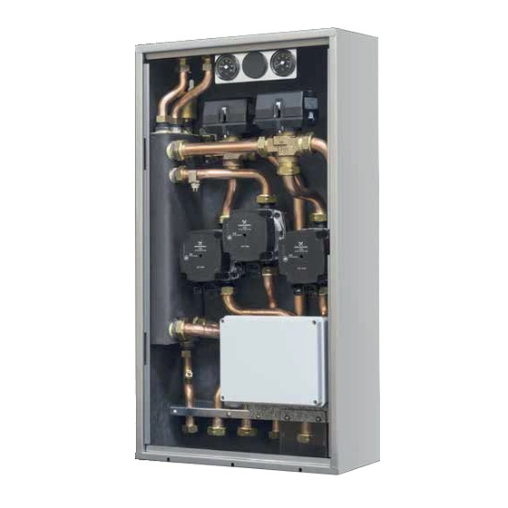
GENERALITÀ 1.4 Struttura DMC A 2VMIX DMC A MIX CLIMA 2 MIX CLIMA Rubinetto di scarico 10 Valvola miscelatrice impianto bassa Bottiglia di miscela temperatura 2 Circolatore impianto bassa temperatura 1 Circolatore impianto bassa temperatura 2 Circolatore impianto alta temperatura... -
Page 5: Dati Tecnici
Verifi care che il vaso d’espansione della caldaia sia di capa- sere accuratamente lavate per rimuovere eventuali residui che cità adeguata alle dimensioni dell’impianto. potrebbero compromettere il buon funzionamento del DMC A. Provvedere a sigillare i fori di passaggio dei tubi di collega- mento dal DMC alla caldaia. -
Page 6: Circolatori
GENERALITÀ 1.8 Circolatori DMC è equipaggiato di circolatori ad alta effi cienza e controllo elettronico le cui prestazioni, da utilizzare per il dimensionamento degli impianti, sono riportate nel grafi co. Prevalenza utile del circolatore Potenza assorbita dal circolatore Portata (m Portata (m Prevalenza residua disponibile all’impianto Prevalenza residua disponibile all’impianto... -
Page 7: Schemi Elettrici
GENERALITÀ 1.9 Schemi elettrici 1.9.1 Schema elettrico DMC A Valvola Valvola miscelatrice miscelatrice zona BT2 zona BT1 Circolatore 1 zona BT1 GI/VE Alimentazione GI/VE elettrica 230V 1 2 3 7 8 9 10 11 12 1314 15 16 17 18 19 20... -
Page 8: Schema Elettrico Dmc A 2Vmix
GENERALITÀ 1.9.2 Schema elettrico DMC A 2VMIX Valvola miscelatrice zona BT1 Circolatore 1 zona BT1 GI/VE Alimentazione GI/VE elettrica 230V 1 2 3 4 5 6 7 8 9 10 11 12 13 14 15 16 17 18 19 20... -
Page 9: Installazione
INSTALLAZIONE 2 INSTALLAZIONE 2.2 Dimensioni e pesi 2.1 Ricevimento del prodotto Il DMC (1) viene fornito in collo unico protetto da un imballo in cartone (2) all’interno del quale si trova una busta di plastica che contiene: − Rampe collegamenti idraulici (3) verso il generatore di ca- lore −... - Page 10 INSTALLAZIONE Per l’installazione del DMC all’interno del box, effettuare le se- − Fissare, utilizzando le apposite clip, i bulbi dei termo- guenti operazioni: metri con questa sequenza (partendo dal lato sinistro): − Inserire il lato destro del DMC all’interno del box e ruotare termometro (T1) alla rampa (C1) posta sotto il circolatore il lato sinistro fi...
-
Page 11: Zone Minime Di Rispetto
INSTALLAZIONE 2.4 Zone minime di rispetto 2.5 Schema di principio installazione tipica La fi gura mostra un esempio tipico di installazione del DMC. NOTA: Per l’installazione di eventuali rubinetti (non forniti) oc- corre predisporre la nicchia di dimensione tale da poterli instal- lare sotto il DMC stesso. -
Page 12: Collegamenti Elettrici
Di seguito verrà spiegato come collegare e confi gurare oppor- late. Per il modello con una sola zona miscelata non considerare tunamente il DMC a seconda del tipo di caldaia, del tipo di im- il collegamento BT2. pianto, della presenza di REC (controlli remoti) e/o TA (termostati Modalità... - Page 13 INSTALLAZIONE I Termostati Ambiente e Cronotermostati devono avere un contatto pulito (libero da potenziale). Modalità STAND ALONE con 3 REC 08 1 2 3 4 5 6 7 8 9 10 11 12 13 14 15 16 17 18 19 20 1 2 3 1 2 3 1 2 3 4 5...
-
Page 14: Modalità Link Mode (Rec)
INSTALLAZIONE 2.6.2 Modalità Link Mode (REC) Modalità LINK MODE con 3 REC 08 La modalità Link Mode è confi gurabile per l’utilizzo del DMC con caldaie in grado di dialogare con protocollo OPEN THERM. 1 2 3 4 5 6 7 8 9 10 11 12 13 14 15 16 17... -
Page 15: Associare Alla Zona Il Relativo Canale
INSTALLAZIONE In caso di alimentazione fase-fase verifi care con un tester quale dei due fi li ha potenziale maggiore rispetto alla terra e collegarlo alla L-Fase, in egual maniera collegare il fi lo ri- manente al N-Neutro. Per alimentazioni fl ottanti, ovvero prive all’origine di riferi- mento a terra è... -
Page 16: Confi Gurazione Del Controllo Remoto Rec Su Canale
INSTALLAZIONE È però possibile associare ad ogni canale la zona idraulica che REC 08 Family REC Ponticello si preferisce così da defi nire per ogni singolo REC, TA o CT quale zona (1-2-3) deve gestire. NON inserito Per associare i canali alle zone idrauliche occorre inserire i pon- ticelli CH1, CH2, CH3 del connettore ST1 seguendo immagine e NON inserito schema di seguito riportati. -
Page 17: Messa In Servizio
MESSA IN SERVIZIO 3 MESSA IN SERVIZIO In presenza Family Remote Control o REC 08 si ha il funziona- mento riportato nel paragrafo “2.6.2 Modalità Link Mode (REC)” . 3.1 Prima messa in servizio 3.3 Temperature Prima di avviare il DMC verifi care la corretta esecuzione dei col- legamenti idraulici ed elettrici. -
Page 18: Temperatura Di Mandata Tra Caldaia E Dmc
MESSA IN SERVIZIO 3.6 Post circolazione Senza termoregolazione da sonda esterna (ponticello ST3-ST4-ST5 non inserito) Le temperature di mandata delle singole zone sono determinate Al termine di una richiesta di calore, da parte di REC, TA o CT, agendo opportunamente sui trimmer di zona (TR1-TR2-TR3) nel sulle singole zone è... -
Page 19: Gestione Antibloccaggio Dei Circolatori
MESSA IN SERVIZIO 3.8 Gestione antibloccaggio dei circolatori 3.11 Impostazione dei circolatori La logica di funzionamento prevede una gestione antiblocco dei DMC è equipaggiato di circolatori elettronici ad alta effi cienza e circolatori e delle valvole miscelatrici. controllo digitale. Di seguito ne verranno descritte le principale Al termine di ogni richiesta di calore su una zona viene attivato caratteristiche e le modalità... - Page 20 MESSA IN SERVIZIO Visualizzazione delle impostazioni attive Con circolatore alimentato, premendo brevemente il tasto (A) è visualizzazione possibile visualizzare la confi gurazione attiva del circolatore. I stato di LED indicano le impostazioni attive . > 2 s impostazione funzionamento In questa fase non può essere fatta nessuna variazione della confi...
-
Page 21: Tabella Parametri
MESSA IN SERVIZIO 3.12 Tabella parametri Prevalenza proporzionale Il circolatore lavora in funzione della domanda di calore dell’im- pianto. Il punto di lavoro del circolatore e la curva di prevalenza Descrizione Valore proporzionale selezionata si sposteranno in funzione della do- Tempo chiusura valvole miscelatrici Power On manda di calore del sistema. -
Page 22: Controlli Dopo La Messa In Servizio
MANUTENZIONE 3.14 Controlli dopo la messa in servizio 4 MANUTENZIONE Una volta completata la messa in servizio dell’apparecchio, ve- 4.1 Pulizia rifi care: − la tenuta dei circuiti idraulici Prima di qualsiasi operazione di pulizia, togliere l’alimentazione − che l’impianto di riscaldamento sia in pressione elettrica posizionando l’interruttore generale su “spento”. -
Page 23: Verifi Ca Delle Valvole Miscelatrici
MANUTENZIONE Effettuare l’operazione con estrema cautela per non dan- neggiare i componenti stessi. È vietato far funzionare i circolatori senza acqua. 4.4 Verifi ca delle valvole miscelatrici Se dopo un lungo periodo di inattività le valvola miscelatrice fosse bloccata è necessario agire manualmente sulla levetta po- sta sul motore in modo da sbloccare l’otturatore della valvola stessa. - Page 24 Wiring diagram ......29 1.9.1 DMC A wiring diagram ......29 1.9.2 DMC A 2VMIX wiring diagram .
-
Page 25: General
(DMC A) or three zones (DMC A 2VMIX) which are at different tem- peratures. It includes a mixing bottle, an electronic board, two/ three circulation units and one/two 3-way mixing valves which control the water temperature in the low temperature zones. -
Page 26: Structure
GENERAL 1.4 Structure DMC A 2VMIX DMC A MIX CLIMA 2 MIX CLIMA Drain cock 10 Mixing valve low temperature system 2 Mixing bottle Circulation unit low temperature system 2 Circulation unit low temperature system 1 12 Electrical connection box... -
Page 27: Technical Data
Electrical protection level with wall mounted installation IP10D Electrical protection level with "built-in" installation IPX4D Maximum pressure 1.7 Plumbing connections The characteristics of the plumbing connections are as follows: DMC A 2VMIX DMC A 2 MIX CLIMA MIX CLIMA Boiler inlet (Ø 3/4”) Boiler outlet (Ø... -
Page 28: Circulation Units
GENERAL 1.8 Circulation units DMC is equipped with high effi ciency electronically controlled circulation units. The performance data of these units to be used to size the system is shown in the graph. Available head of the circulation unit Power absorbed by the circulation unit Flow rate (m3/h) Flow rate (m3/h) Residual head available to the system... -
Page 29: Wiring Diagram
GENERAL 1.9 Wiring diagram 1.9.1 DMC A wiring diagram Mixing Mixing valve valve zone BT2 zone BT1 Circulation unit 1 zone BT1 GI/VE 230V power GI/VE supply 1 2 3 7 8 9 10 11 12 1314 15 16 17 18 19 20... -
Page 30: Dmc A 2Vmix Wiring Diagram
GENERAL 1.9.2 DMC A 2VMIX wiring diagram Mixing valve zone BT1 Circulation unit 1 zone BT1 GI/VE 230V power GI/VE supply 1 2 3 4 5 6 7 8 9 10 11 12 13 14 15 16 17 18 19 20... -
Page 31: Installation
INSTALLATION 2 INSTALLATION 2.2 Dimensions and weights 2.1 Receiving the product The DMC (1) is supplied in one package, protected by cardboard packaging (2) inside of which there is a plastic envelope con- taining: − Plumbing connection ramps (3) towards the heat gen- erator −... - Page 32 INSTALLATION To install DMC inside the box, proceed as follows: − Using the designated clips, secure the thermometer bulbs − Insert the right side of the DMC inside the box and rotate following the sequence (from left to right): thermometer the left side until the DMC enters completely making sure (T1) to the ramp (C1) located below the BT1 system circula- that the insulator covering the mixing bottle is not dam-...
-
Page 33: Minimum Distances
INSTALLATION 2.4 Minimum distances 2.5 Typical installation layout The fi gure shows an example of a typical installation of the DMC. N.B.: For the installation of any cocks, (not supplied), a niche must be formed of a suffi cient size to allow them to be fi tted below the DMC itself. -
Page 34: Electrical Connections
INSTALLATION 2.6 Electrical connections STAND ALONE: − CAN BE COMBINED WITH ALL BOILERS The DMC is prearranged with rubber cable feed-throughs (1) lo- − HEAT REQUEST TO THE BOILER WITH DRY CONTACT cated in the top section of the box allowing wiring to be passed −... -
Page 35: Link Mode (Rec)
INSTALLATION 2.6.2 Link Mode (REC) SSTAND ALONE mode with 3 REC 08 Link Mode can be confi gured to use the DMC with boilers able to communicate with OPEN THERM. protocol. In this mode, the DMC 1 2 3 4 5 6 7 8 9 10 11 12 13 14 15 16 17... -
Page 36: Associating The Zone To The Corresponding Channel
INSTALLATION LINK MODE When using a phase-phase power supply, use a tester to with 3 REC 08 determine which of the two wires has the greater potential compared to the earth and connect it to the L terminal. Con- nect the remaining wire to the N terminal. 1 2 3 4 5 6 7 8 9 10... -
Page 37: Confi Guration Of The Rec Remote Control On Channel 1
INSTALLATION 2.9 External sensor It is however possible to associate each channel to the desired water zone in order to defi ne which zone (1-2-3) each individual REC, TA or CT is to control. Please refer to the indications provided in the boiler manual To associate the channels to the water zones, the jumpers CH1, to correctly position the external sensor. -
Page 38: Commissioning
COMMISSIONING 3 COMMISSIONING DMC and the system” . 3.1 First start-up 3.3 Temperatures Before starting up the DMC, check that the plumbing and electri- This section describes how the delivery temperatures of the in- cal connections have been carried out correctly. dividual zones of the heat generator can be managed. -
Page 39: Delivery Temperature Between The Boiler And The Dmc
COMMISSIONING 3.6 Post circulation Without thermoregulation by the external sensor (jumper ST3-ST4-ST5 not inserted) The delivery temperatures of the individual zones are deter- At the end of a heat request, by the REC, TA or CT on the individual mined by acting appropriately on the trimmer (TR1-TR2-TR3) of zone, post circulation is carried out for 30 seconds during which the zone as described : time the circulation unit of the zone will be powered. -
Page 40: Circulation Units Anti Block Control
COMMISSIONING 3.8 Circulation units anti block control 3.11 Setting the circulation units The operating logic includes an anti block control of the circula- The DMC is equipped with digitally controlled high effi ciency tion units and mixing valves. electronic circulation units. Below is a description of the main At the end of each heat request on a zone, a corresponding tim- characteristics and the procedures to be carried out in order to er lasting 24 hours is activated. - Page 41 COMMISSIONING Active settings display With the circulation unit powered, briefl y press the button (A) Proportional head LED 1 LED 2 LED 3 LED 4 LED 5 to see the active confi guration of the circulation unit. The LEDs green yellow yellow yellow...
-
Page 42: Parameter Table
COMMISSIONING 3.13 Alarm list Constant curve The circulation unit works at constant speed, irrespective of the heat request from the system. The working point of the circula- The following table shows the alarms of the DMC board which tion unit will move along the selected curve on the basis of the are transmitted to the REC. -
Page 43: Maintenance
MAINTENANCE 4 MAINTENANCE Do not run the circulation unit without water. 4.1 Cleaning 4.4 Checking the mixing valves Disconnect from the power supply before carrying out any clean- ing operation by setting the main switch to "off". The panelling is to be cleaned with a damp cloth using soap and If the mixing valve is blocked after a long period of inactivity, water. - Page 46 INSTALLATION...
- Page 48 Via Mussa, 20 Z.I. - 35017 Piombino Dese (PD) - Italia Tel. 049.9323911 - Fax 049.9323972 - www.thermital.it - email: info@thermital.it da è costantemente impegnata nel continuo perfezionamento di tutta la sua produzione, Poichè l’ A zien le caratteristiche estetiche e dimensionali, i dati tecnici, gli equipaggiamenti e gli accessori, possono essere soggetti a variazione.
Need help?
Do you have a question about the DMC A and is the answer not in the manual?
Questions and answers