
Subscribe to Our Youtube Channel
Related Manuals for Vimar ELVOX K40980


Summary of Contents for Vimar ELVOX K40980
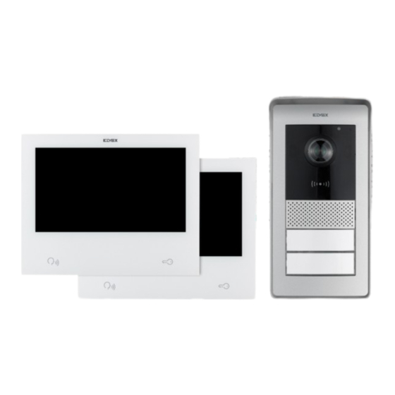
- Page 1 User Manual K40980 - K40981 IP-over-2Wires 7" Touch screen Wi-Fi one-family/two-family video door entry kit...
-
Page 2: Table Of Contents
K40980 - K40981 Index • System ....................................3 • Indoor Station ..................................4 • Functions ................................... 4 • Technical data ..................................4 • Entrance panel ..................................5 • Functions ................................... 5 • Technical data ..................................5 • Power supply unit ................................6 •... -
Page 3: System
K40980 - K40981 System In general, the IPo2W system allows video door entry devices to communicate with each other via the TCP/IP protocol, using a connection over non-polarised 2-wire cables. The system can also interface with IP cameras via Wi-Fi. The system offered is composed of: - Outdoor Station. One outdoor station can be connected. The outdoor station can be configured to communicate with two apartments. - Indoor Station. One or two indoor stations can be installed in an apartment. - System power supply unit. One outdoor station and two indoor stations per apartment can be connected, for up to two apartments. Assuming that the system power supply unit is the device at the centre of the video door entry system, outdoor stations and indoor stations can be connected to the power supply unit with a star topology, a daisy-chain connection (or input to output) or a mixed connection (star and daisy-chain). -
Page 4: Indoor Station
K40980 - K40981 Indoor Station Functions • 7" capacitive touch screen monitor • IEEE 802.11 b/g/n 2.4GHz Wi-Fi connectivity • Possibility of receiving firmware upgrades via OTA (Over The Air) • Remote calls via the VIEW Door App on one or more smartphones • Actuator enable/disable (powered lock and gate relay or other actuator) • Internal flash memory and micro SD card support • Automatic and manual video/image recording • Voice message • Intercom function between indoor stations of the same apartment and between groups of indoor stations of different apartments. • Full-duplex audio with echo cancellation and noise reduction functions • Adjustable conversation and ringtone volumes • Selectable ringtone (for outdoor station, intercom, landing) • Adjustable ringtone duration (for outdoor station, intercom, landing) • “Do not disturb” function • Landing call button mounting frame • Mounting frame for optional IP cameras • Voice assistant mounting frame (Amazon Alexa) • Device with multi-lingual support • On-case touch button for preview; on-case touch button for lock; 4 on-case status icons (messages, Wi-Fi disconnected;... -
Page 5: Entrance Panel
K40980 - K40981 Entrance panel Functions • Two-wire audio-video unit with wide angle lens camera • CMOS video sensor with 2Mpx resolution • H.264 video compression with Full HD resolution (1920 x 1080) • 160° horizontal wide angle lens • Full-duplex audio with echo cancellation and noise reduction functions • 2 IR LEDs for night vision • Protection degree: IP54 • Protection degree against impact: IK07 • Aluminium housing • Speaker volume adjustment • Name plate for single or double apartment systems, backlit with call button • Rain-proof frame • Electric lock and/or relay control mounting frame • RFID reader • Surface installation Technical data • Operating temperature: (-25 °C; +55 °C) • Dimensions (mm) 101.3 (L) x 198.8 (H) x 43.8 (D) (with rain-proof frame) 95.5 (L) x 190 (H) x 33 (D) (without rain-proof frame) -
Page 6: Power Supply Unit
K40980 - K40981 Power supply unit The kit includes a DIN rail system power supply unit for installation in the control unit. Refer to the following pages for the technical characteristics. Technical Data • System power supply unit • Input: 100 – 230 VAC • Output: 32 VDC, 3.5 A max • Status LED: red indicates that the power supply unit is on... -
Page 7: App
K40980 - K40981 Functions • A MyVimar account is needed to use the VIEW Door App with IPo2W devices • Available for both Android (Android 5.1 and later) and iOS (iOS 9.0 and later) systems • Support for audio/video calls from outdoor stations • Function for consulting IP cameras connected • Audio/video preview from outdoor stations • Support for audio calls from and to indoor stations • List of calls received function • Image and/or video save function from calls or consultation. • Multi-device management function • Remote lock or relay activation • Communication time setting from 60s to 300s • Auto-rotate image function • Ability to set image quality: HD - SD - LD • Zoom function support... -
Page 8: Indoor Station
K40980 - K40981 Indoor Station... - Page 9 K40980 - K40981 1 - display 2 - microphone 3 - preview button (backlit) 4 - backlit alert icons a) messages; b) Wi-Fi connection not active; c) lock activation; d) DND (Do Not Disturb) function active; 5 - terminal for landing call button 6 - terminal for future use 7 - connector for future use 8 - lock actuation button 9 - slot for SD-card (note: the SD-card should be slotted in from the connection terminals side, making sure the terminals are facing towards the user). 10 - Speaker 11 - Connector (BUS IN; BUS OUT; DC IN – for future use)
-
Page 10: Outdoor Station
K40980 - K40981 Outdoor Station... - Page 11 K40980 - K40981 1 - luminous indicators (from right to left): a) communication status indicator. Flashing green light: call in progress; Continuous green light: communication in progress. b) Lock or relay status indicator. Green light on: lock or relay active. c) System status indicator. Continuous red light: system occupied. 2 - IR LED for night vision 3 - NFC card reader 4 - speaker 5, 6 - call buttons (configurable for one-family or two-family building) 7 - camera 8 - “Brightness” sensor 9 - microphone 10 - IR LED for night vision 11 - anti-vandal screw...
-
Page 12: Video Door Entry System Installation
K40980 - K40981 Video door entry system installation General considerations: The procedure to follow when installing a IPo2W video door entry system for one or two families is described below. 1) Before activating the video door entry system, take care to find a suitable location for each component, i.e. power supply unit, outdoor station and indoor station. Moreover, configure the outdoor stations first using the dip switches (master/slave device; assign ID, number of buttons and default actuator to activate the lock from the exit push button or from the lock release push button). 2) Make sure you connect the outdoor station and each indoor station to the system power supply unit. Connection cables that can be used: o Two-wire cable with a section of 1 or 1.5 mm : maximum distance between the power supply unit and farthest device: 150 o UTP Cat. 5e or Cat. 6 cable with 4 twisted pairs: maximum distance between the power supply unit and farthest device: 120 m. 3) Always connect every device in the installation before activating the system, i.e. connect the power supply unit to the mains power. 4) Check that the components are activated correctly: a. the system power supply unit is active if the red status LED is on b. the outdoor station is active if covering the light sensor turns on the call button backlighting c. the indoor stations are active if the display is active and ready for configuration at the end of the boot procedure (activation takes about 20s) 5) The video door entry system can be used once the indoor stations have been configured. Note: in an IPo2W system, the indoor stations must be the last devices to be configured. In fact, to operate correctly, these devices must detect the outdoor station with which to interact while they are being configured. -
Page 13: Considerations For Connection
K40980 - K40981 Considerations for the connection As explained at the beginning, various different connection types can be used with the IPo2W system: - Star - Daisy chain (or input to output) - Mixed (star and daisy chain) The power supply unit label shows that: 1) At the top of the device there is an input port with terminals protected by a plastic case, for the mains power connection. The neutral terminal is identified with the letter (N); the line terminal is identified with the letter (L). 2) At the bottom of the device there is a port for connecting the 2-wire BUS for IM (Indoor Monitor or indoor station) and a port for connecting the 2-wire BUS for OS (Outdoor Station). Each port has a “+” terminal and a “-” terminal. We recommend connecting cables of the same colour to the “+” and “-” terminals. Connect the 2-wire BUS cables from the + and - terminals of the IM port on the power supply unit to the corresponding terminals of the BUS_IN port on the indoor monitor. Connect the 2-wire BUS cables from the + and - terminals of the OS port on the power supply unit to the BUS+ and BUS- terminals of the 2-wire BUS port on the outdoor station. Remember that the 2-wire BUS of the IPo2W system is non-polarised, so there is no need to connect the terminals at the indoor station/outdoor station end in a particular order. -
Page 14: Power Supply Unit Installation
K40980 - K40981 Power Supply Unit Installation The power supply unit is installed by securing it to a DIN rail, and is compatible with Vimar control units. A red LED indicates when the device is operating correctly; when the LED is on, it is working normally. 40105 INPUT (L/N):~100-240V 50/60Hz 2.5A OUTPUT (+/-):32V 2.5A CONT+1A INT INT: 90s ON/180s OFF (OS) 40105 INPUT (L/N):~100-240V 50/60Hz 2.5A 40105 OUTPUT (+/-):32V 2.5A CONT+1A INT INPUT (L/N):~100-240V 50/60Hz 2.5A INT: 90s ON/180s OFF... -
Page 15: Outdoor Station Installation
K40980 - K40981 Outdoor Station Installation The outdoor station can be installed on a wall surface with or without the rain guard provided. When installing the device, take care to open the front case by loosening the fixing screw on the underside of the front cover plate, using the security key provided. Fasten the base of the outdoor station, with or without rain guard, to the wall with the 4 screws and 4 wall plugs provided. We recommend fastening the device as set out below. In order to operate, the outdoor station must be connected to the system bus. The connection can be made by connecting the bus to the BUS+ and BUS- connectors. - Page 16 K40980 - K40981 102,5 43,8 95,5...
- Page 17 K40980 - K40981 7 7 , 2 2 , 2 2 ,...
- Page 18 K40980 - K40981 VIMAR V I M V I M V I M B I A B I A V I M V I M R O S R O S...
-
Page 19: Outdoor Station Configuration And Connection
K40980 - K40981 Outdoor Station Configuration and Connection In order for the outdoor station to operate, make sure you connect the bus to the BUS+ and BUS- (non-polarised) terminals. To complete the installation, note that the following can be connected: the GND and LOCK terminals to control an electric lock the COM and NO/NC terminals to control an actuator using a relay with NO or NC contact. The relay mode is defined by the position of the jumper on the side: - jumper placed between the upper pair of PINs: NO (normally open) mode - jumper placed between the lower pair of PINs: NC (normally closed) mode - the GND and EXIT terminals to connect one or more door release buttons (NO push buttons). Exit Power button lock EXIT LOCK Configuration dip-switch Reset Volume adjustment (prog) BUS+ BUS- NO/NC NC/NO 2-wire Relay relay To complete the description of the functions that can be set during installation, note that the audio volume can be adjusted with the potentiometer. - Page 20 K40980 - K40981 Some special functions can be configured with the dip switches at the top right: dip 1: on: the outdoor station is configured as the “master” outdoor station (note: in every system, only one outdoor station configured as “master” is necessary; the outdoor station supplied in the one-family and two-family kits is configured as the “master” by default). Default value: 1 dip 2-3: pair of switches to configure outdoor station ID (note: the outdoor station supplied in the one-family and two-family kits is configured as outdoor station “1” by default). Default values: 00 dip 4-5: pair of switches to configure the number of push buttons used (note: the outdoor station supplied in the one-family kit is configured for 1 push button by default; the outdoor station supplied in the two-family kit is configured for 2 push buttons by default). Default values: 00 for one-family system; 10 for two-family system. dip 6: switch to configure the lock release button on the front of the indoor station. If switch 6 is “ON”, the defined lock is the relay; if switch 6 is “OFF”, the defined lock is the powered one. Switch 6 is configured to “OFF” by default, i.e. the powered lock is the default lock. (ON) (OFF) Note that: - for one-family outdoor stations, the call button can only be configured for apartment 1.
-
Page 21: Configuring The Administration Keys
K40980 - K40981 The outdoor station is also equipped with an NFC tag reader. To use NFC keys, the RFID reader must be configured. Note: the following configuration is only possible if the outdoor station is powered, i.e. if it is connected to the system bus. The RFID configuration procedure is described below. Configuring the administration keys 1) Press the reset push button on the outdoor station twice quickly; the device will respond with a sequence of 4 beeps (the configuration procedure starts from this moment). 2) Bring the first key up to the RFID reader; the device will emit a long beep; the first key is configured as “administration key for addition”. Note: we recommend marking the key with “key for addition” 3) Bring the second key up to the RFID reader; the device will emit a long beep; the second key is configured as “administration key for removal”. Note: we recommend marking the key with “key for removal”. The front case can now be installed on the outdoor station, taking care to close the anti-tamper key. Adding a user key 1) Bring the “administration key for addition” up to the RFID reader; the device will beep. 2) Bring an unprogrammed key up to the reader. The device will enable it as a “user key”. The device will beep when the configuration is complete. 3) Repeat step 2) to add any other keys. 4) The procedure for enabling user keys will terminate after about 5s of inactivity. The device will beep 4 times to indicate the end of the procedure. Removing user keys 1) Bring the “administration key for removal” up to the RFID reader; the device will beep. 2) Bring a user key up to the reader. The device will disable it. The device will beep when the configuration is complete. 3) Repeat step 2) to remove any other keys. 4) The procedure for disabling user keys will terminate after about 5s of inactivity. The device will beep 4 times to indicate the end of the procedure. -
Page 22: Indoor Station Installation
K40980 - K40981 Indoor Station Installation The indoor station can be installed on a wall surface. Note that the indoor station is supplied complete with a bracket that is compatible with flush mounting boxes: - Mounting box 7249 (with bracket 40196) - Round mounting box 2M V71701 - Horizontal/vertical mounting box 3M V71703, V71303 - British Standard square mounting box Use the screws and wall plugs provided in the kit to install the bracket on the wall. In order to operate, the indoor station must be connected to the system bus. The connection to the system bus must be made either directly via the power supply unit bus or via the bus of another indoor station. 184,3 155,2 25,3 24,5... - Page 23 K40980 - K40981 8 3 , 8 3 , 8 3 ,...
- Page 24 K40980 - K40981 BUS IN BUS IN BUS OUT BUS OUT DC IN...
- Page 25 K40980 - K40981...
-
Page 26: Indoor Station Configuration
K40980 - K40981 Indoor Station Configuration As explained previously, the indoor station can only be configured after installing all the system devices, connecting them, and configuring the outdoor station. To configure the indoor station, power up the video door entry system. The indoor station will take a few tens of seconds to activate. Once it is active and ready for configuration, the following screen will appear on the indoor station in order to choose the language: Ελληνικά Nederlands English Italiano Français Figure 11 1) Choose the language you intend to use when configuring and using the device; tap your chosen language and tap the tick at the bottom right (see Fig 11). user Figure 12 2) The screen shown above then appears (Fig. 12). Enter the following in order: a) User name. Remember that, in an apartment with several devices, this name distinguishes each indoor station from the others. Within a multi-apartment system, the group relating to each apartment is identified by the user name of the “master” device in the respective apartment. b) Apartment number. c) Extension number, i.e. the number that identifies the indoor station being configured. - Page 27 K40980 - K40981 Note that to operate correctly, the IPo2W video door entry must have one and only one “master” indoor station. The master indoor station of each apartment must be identified with the number “1”. If there is an additional indoor station, it will be identified with the number “2”. Note that you can tap the bottom left arrow to return to the previous page, if necessary. After entering the required data, tap the tick at the bottom right. When configuring the first indoor station as the system “master” (meaning the apartment master configured first chronologically), the configuration procedure will prompt you for the time zone as shown in the figure below. When configuring a device that is not identified as the first apartment master (i.e. the first master configured), the date, time and time zone will be configured automatically to be the same as in the first master (system master). Figure 13 3) Select the time zone as shown in Fig. 13. Note that you can tap the bottom left arrow to return to the previous page, if necessary. After selecting the time zone, tap the tick at the bottom right. Figure 14...
- Page 28 K40980 - K40981 4) The indoor station identified as the apartment “master” will prompt you to configure the date and time. After entering the information, tap the tick on the right. Figure 15 5) The system will start the configuration phase, as shown above in Fig. 15. If the system recognises that more than one device within the same apartment have the same identification number (same extension number), the indoor station will show the page in Fig. 16. If the system confirms that each indoor station within the same apartment has its own unique identification number (extension number), the indoor station is fully configured and the configuration successful page will appear on the indoor station, as shown in Fig. 17 Figure 16...
- Page 29 K40980 - K40981 Figure 17 6) Configuration completed successfully. Figure 18 7) When the configuration is complete, the indoor station will reboot as shown above. After rebooting (which takes a few tens of seconds), the home page will appear on the indoor station as shown in the page below: Figure 19...
-
Page 30: Indoor Station: Home Page
K40980 - K40981 Indoor Station: Home page State icons Primary Date and time functions Secondary functions Figure 20 The indoor station home page is organised to provide the most important information for using the video door entry device and accessing the various functions. Status icon (area encircled in yellow) speaker status: the speaker is muted in this case SD card status: this icon indicates that an SD card is inserted in the slot cloud connection status: this icon indicates whether the cloud connection is active correctly (for the master monitor only) monitor connection status and signal strength indicator (for the master monitor only) Date and time (area encircled in red) - Time and Date (the time is synchronised automatically if the video door entry system is connected to the internet) -
Page 31: Primary Functions (Area Encircled In Blue)
K40980 - K40981 Primary functions (area encircled in blue) Consult Outdoor Stations Consult Contacts Consult list of calls Consult list of recordings Secondary functions (area encircled in white) Icon to activate/deactivate the DND (Do Not Disturb) function. Note that once the DND function is activated, it mutes the video entryphone for the whole day by default. It is possible to set a daily time slot during which the DND function is active (the DND function is deactivated by default). Icon to activate/deactivate the automatic recording of the photo or video of the caller for each call of the outdoor station. Icon to call all mobile phones connected to the indoor station. Icon to activate/deactivate the voice message service. When activated, a call from the outdoor station will be followed by a predefined or custom audio message. The guest can leave an audio message (the voice message service is deactivated by default). Icon to access the device or video door entry system settings. -
Page 32: Primary Functions: Details
K40980 - K40981 Primary functions: details Consult Outdoor Stations: tap this icon to consult the master outdoor station in preview mode. The preview page is shown below: Figure 21 The preview page contains a row of touch controls. Note that the row of controls is hidden automatically; just tap the display to make it reappear. The icons on the bottom bar have the following functions: icon to take a photo of the screen contents icon to make a video recording (with a minimum duration of about 15s) of the screen contents icon to adjust the conversation audio volume as shown in the figure below... - Page 33 K40980 - K40981 Figure 22 icon for the mute function icon to end the communication icon to consult the secondary Outdoor Stations icon to consult IP cameras icon to activate the lock (tap the icon to bring up a bar from which you can activate either the lock or relay).
- Page 34 K40980 - K40981 Consult Contacts: the indoor stations in an IPo2W system generally offer an intercom function: o Between devices in the same apartment o Between devices in different apartments Intercom calls can be made by selecting one of the contacts. Devices in the same apartment are identified by an icon with a star and the device name. Devices in a second apartment, if there is one, are only shown as an apartment group, and are identified by an icon without a star and with the name of the master device in the second apartment. In a recently configured IPo2W system composed of multiple indoor stations, all devices can communicate with the other indoor stations by default (regardless of whether they are in the same apartment or a different one). Note that the indoor station intercom function is available between users that have each other among their contacts. If a user wants to prevent intercom communication with a specific user, they just have to remove the unwanted user from their contacts using the menu that can be opened with icon at the top right. Removing the contact the will prevent calls between the two users, in either direction. To make an intercom call to a contact, tap the icon corresponding to the contact concerned. To remove a contact, just touch the related icon for a long time; a window will appear to prompt you to confirm that you want to remove the contact concerned. To add a contact removed previously, just tap the icon at the top right; this will open a menu in which you can activate/ deactivate contacts for intercom calls. Consult list of calls Tap the “Calls” icon to open the list of calls in chronological order. Each call is identified by a line containing the following in order: an icon that identifies whether the call was incoming or outgoing, and if the call was answered or not; name of the device from which the call was made; the date and time of the call; link to a photo/video/audio message, if available. Figure 23...
- Page 35 K40980 - K40981 Messages can be deleted by touching the call line for a long time and selecting the remove option. Consult list of recordings Tap the “Recordings” icon to open the list of recordings (in picture or video format) in chronological order. Each recording is identified by a line containing the following information: Figure 24 icon of the device from which the pictures were taken; the device identification; the date and time at which the recording was made. Recordings can be deleted with the “bin” icon at the bottom right of the page. Note: if the “Auto delete” function is active, it deletes all recordings made more the 30 days ago. Prolonged tapping on a recording will open a window with the following functions: - removal of the individual recording - removal of all the recordings - copy of recordings onto an SD-card...
-
Page 36: Secondary Functions: Details
K40980 - K40981 Secondary functions: details Icon to activate/deactivate the DND (Do Not Disturb) function; tap this icon to activate/deactivate the DND function. Icon to activate/deactivate the automatic recording of the photo or video of the caller for each call from the outdoor station. Icon to call all mobile phones connected to the indoor station. Icon to activate/deactivate the voice message service. Icon to access the device/system settings Tap the “Settings” icon to open the settings menu shown in Fig. 25. Figure 25 The meaning of each icon in the menu is explained below: opens the “General Settings” sub-menu... - Page 37 K40980 - K40981 The functions that can be consulted and configured via the “General Settings” sub-menu are listed below; the functions appear in two different pages: Figure 26 Figure 27 • System Info: page containing the main information about the indoor station, including the firmware version, apartment number and extension number (Fig. 28). Figure 28...
- Page 38 K40980 - K40981 • Language: page for configuring the user language of the indoor station. Ελληνικά Nederlands English Italiano Français Figure 29 • Date Format Setting: page for configuring the date format. Figure 30 • Clean Mode: page for activating the device cleaning mode (we recommend activating this mode before cleaning the device to avoid setting functions accidentally). Figure 31...
- Page 39 K40980 - K40981 • Backlight Settings: page for activating/deactivating the button backlighting. This page can also be used to configure the time-out of the indoor station display. Figure 32 • User Reset: page containing the following options: a) Reset the user settings b) Restart the device c) Format the SD-card Note: it will not be possible to receive and answer calls while the device is restarting. Figure 33...
- Page 40 K40980 - K40981 • Voice message: page for configuring a voice message that the outdoor station will play following a call. As shown in the figure below, firstly the audio playback mode can be configured; secondly, you can record your own voice message. Figure 34 a) Voice message playback mode Figure 35 b) Record audio message Figure 36...
- Page 41 K40980 - K40981 • Customized Background: page for configuring the background picture for the home page. opens the ringtone configuration page Figure 37 Figure 38 • Beep sound: activates/deactivates an acoustic signal on every key press...
- Page 42 K40980 - K40981 • Ringtone-volume: page for configuring the call ringtone Figure 39 • Talk volume: page for configuring the audio communication volume Figure 40 • Entry panel ringtone: page for choosing the ringtone for calls from the outdoor station Figure 41...
- Page 43 K40980 - K40981 • Intercom ringtone: page for choosing the ringtone for calls from the indoor station Figure 42 • Landing call ringtone: page for choosing the ringtone for calls from the landing push button Figure 43 • Ring time: page to configure the ringtone duration for calls from the following, respectively: - Outdoor Station - Intercom - Landing Push Button Figure 44...
- Page 44 K40980 - K40981 opens, first of all, the DND (Do Not Disturb) function activation page Figure 45 It is then possible to set the daily time slot for the DND function (the time slot is the whole day by default). Figure 46 opens the Wi-Fi configuration page. This function is only available for master indoor stations. Connecting the Master Indoor Station to a Wi-Fi network allows you to: - connect the video door entry system to one or more smartphones using the “VIEW Door” App - receive any fw updates for the Indoor Station and Outdoor Station The availability of fw updates is signalled by a notification dot on the “Settings” icon on the home page and the related sub-icons leading up to the fw update icon. N.B.: In order to ensure the IPo2W system is in the best operating and security conditions, we recommend checking for any available fw updates and installing them.
- Page 45 K40980 - K40981 The first page shows the functions for connecting the indoor station to the Wi-Fi, configuring the call forwarding service to the App, removing connected Apps and resetting the Wi-Fi factory setting. Figure 47 The second page shows the QR code to find the App in the Android and iOS stores, and the QR code to connect the indoor station to the App. Info: The procedure for Indoor Station configuration via App, using the “pairing” QR-Code is explained in detail in the chapter entitled "App: Configuration” below. Figure 48...
- Page 46 K40980 - K40981 In detail: • Wi-Fi Configuration: page for connecting the monitor to the Wi-Fi network Figure 49 • Call forwarding delay: page for configuring the call forwarding delay from the indoor station to the App Figure 50 • Remove connected Apps: page for removing accounts to which the indoor station is connected Figure 51...
- Page 47 K40980 - K40981 • Wi-Fi factory settings: page for resetting the Wi-Fi Figure 52 opens the IP camera configuration page. Tap the “+” icon to add an IP camera Figure 53 Be sure to fill in the fields in the next page: Figure 54...
- Page 48 K40980 - K40981 The IPo2W video door entry system is compatible with certain Elvox IP cameras: for the list of compatible cameras, please consult the product page of the video door entry kit on the company website. The Elvox IP camera must belong to the same IP network as the indoor station concerned, and must have a fixed IP address (static and reserved by the DHCP server) so that the IP address uniquely identifies the camera in the IP network. Configuration consists of assigning an identification “Label” to each camera and entering the unique IP address reserved for the camera. You will also have to enter the consultation credentials in the IP camera configuration page; the camera user manual should specify the username and password to use for communication with the camera; enter the same username and password in the corresponding fields shown in the figure above. To complete the configuration, specify the correct H.264 video stream (major stream or sub stream). You can find detailed instructions for configuring cameras in the camera User Manual. The camera User Manual can be found in the related product page in the Vimar company website. opens the system configuration sub-menu. This sub-menu is password-protected. The default password to access system configuration is “0000”. To keep the system settings confidential, we recommend customising the password and noting it down in a secure place or remembering it. The functions that can be consulted and configured via the “Installer Settings” sub-menu are listed below: Figure 55...
- Page 49 K40980 - K40981 Monitor Settings: page for configuring the indoor station • Figure 56 The “Monitor Settings” page will grant access to the following pages: • Software Update: page for the fw update of the indoor station Figure 57 Address Settings: page for configuring the indoor station address: • user Figure 58...
- Page 50 K40980 - K40981 • Password Settings: pages for updating the installer’s password Figure 59 • Factory Reset: page for resetting the indoor station (the reset will reset the indoor station to the original factory settings): Figure 60 Note: if it is necessary to perform a factory reset on the entire video door entry system, we recommend the following procedure: 1) Perform a factory reset of the slave monitors 2) Perform a factory reset of the master monitors 3) Update the dip switch configuration if necessary 4) Perform an ordered factory reset of the entrance panels, from the entrance panel with ID “1” onwards. 5) Wait 1 minute...
- Page 51 K40980 - K40981 • Time Settings: page for configuring the system date and time Figure 61 • Timezone: page for configuring the time zone Figure 62 • Door Panel Settings: page for configuring the outdoor station Figure 63...
- Page 52 K40980 - K40981 The “Door Panel Settings” page will grant access to the following pages: • Software Update: page for verifying the firmware version installed in the outdoor station and managing updates. Figure 64 The fw update of the outdoor station can be carried out on this page, where available. When the update procedure is launched, we recommend you wait for it to be completed before proceeding with the same operation on another device. • Tamper Switch Enable: page for enabling the anti-tamper sensor in the outdoor station Figure 65...
- Page 53 K40980 - K40981 • Vocal Message Settings: page for activating/deactivating vocal message or acoustic feedback Figure 66 Figure 67 • Vocal Message Volume: page for configuring the volume of vocal messages Figure 68...
- Page 54 K40980 - K40981 Figure 69 • Lock Settings: page for configuring the outdoor station actuators Lock1: electric lock. The configurable time is for the maintenance current duration (electric current of 200mA). Lock2: relay. The configurable time is for the activation duration. Exit button: external push button to release the default lock. The configurable time is related to the delay between pressing the external push button and the activation of the default lock. Figure 70...
- Page 55 K40980 - K40981 • PLC: page with operating parameter values in the PLC module Note: correct device operation usually requires a AGC value between -20 and +20. Values outside this range may indicate issues with the system wiring. Figure 71...
-
Page 56: App: Configuration
K40980 - K40981 App: Configuration 1) In order to be connected to the VIEW Door App, the device requires a MyVimar account. If the account is not available, create one at the link: https://www.vimar.com/en/int/user/login (the account can be created both on the web and using the App). 2) Check that your monitor is connected to the internet. 3) Activate the App: the App will display the page shown below (Fig.71): Figure 71 4) Tap on “Login”: the page shown in Fig will be displayed. 72. Figure 72... - Page 57 K40980 - K40981 5) Tap on the bottom (Go to MyVimar login”) to go to the account login page Fig. 73. If you do not have a MyVimar account yet, create it by tapping the link “Want to create a profile? Do you want to manage your profile?” which takes you to the MyVimar website. Figure 73 6) Once you have logged into your account, the “Devices” page is displayed, as shown in Fig. 74: Figure 74...
- Page 58 K40980 - K40981 7) To connect the device, touch the central “+” icon to open the page shown in Fig. 75. As can be seen in the image, the camera has been activated; frame the QR code with the box shown by the App. in the QR code can be found on the indoor station, at this path: display > Settings > Wi-Fi (second page of the pager, see figure 48). Figure 75 8) Scan the QR Code, the App will recognise the code and the page shown in Fig will be displayed. 76 Figure 76...
- Page 59 K40980 - K40981 As soon as the App has identified the device via the cloud, it will prompt you to confirm that you want to add the device to the “devices” connected to the App. Figure 77 10) The App will then prompt you for the device a name; this name will identify the device among the other “devices” on the App. Figure 78...
- Page 60 K40980 - K40981 11) Tap “Save” to confirm that you want to connect the device to the App. For security, the App will then prompt you to enter a numerical password for the device, as shown in the following figure. Note: we recommend remembering the newly set device password. Should you wish to share the device with another user, they will have to use the same password. Figure 79 12) Once the “device password” has been confirmed, the new device will appear in the list of “devices” connected to the App. Door Panel 1 17:52:45 23.10.2022 Figure 80...
- Page 61 K40980 - K40981 13) Tap the three dots at the top right of the connected device page to open the window shown in the image below: Door Panel 1 17:52:45 23.10.2022 Figure 81 14) The window offers two options: a. Setting: opens the device configurations available on the App. b. Share: the first user to configure the device can manage or administer the device and share it with other users for use and consultation, provided they have a MyVimar account. To share the device, enter the email address that the user has linked to the MyVimar account. Tap the “Setting” option to open the “Device settings” page shown in the figure below. Figure 82...
- Page 62 K40980 - K40981 As can be seen in the figure above, the page offers the following options: a) Device name: tap this to open a window in which you can edit the device name. b) Device details Figure 83 Note: if a fw update is available, a coloured symbol will appear next the fw version. The update should be activated from the dedicated monitor menu. c) Share device Figure 84...
- Page 63 K40980 - K40981 The first user to configure the device can manage or administer the device and share it with other users for use and consultation, provided they have a MyVimar account. To share the device, enter the email address that the user has linked to the MyVimar account. d) Push settings As shown in the image below, the following alerts can be activated: o Call alerts o Tamper alert Figure 85 e) Advanced settings As shown in the image below, the following options are available: o Modify device password o Activate/deactivate shortcuts o Activate/deactivate thumbnails o Configure the preview/conversation time limit...
- Page 64 K40980 - K40981 Figure 86 f) Remove the device from the App Tap “Delete” to remove the device from the App.
-
Page 65: App: Use
K40980 - K40981 App: use You can consult the device connected to the App from the “Devices” section Door Panel 1 17:52:45 23.10.2022 Figure 87 Tap the image of the device to activate the preview, as shown in the image below: Door Panel 1 19:30:24 23.10.2022 Figure 88... - Page 66 K40980 - K40981 As can be seen in the previous image, the following functions are available during the preview: time-line icon: consults the recording of call from the outdoor station audio communication icon: activates communication with the outdoor station lock icon: activates the lock (electric lock or relay)
-
Page 67: Ipo2W Devices - Alexa: Integration
K40980 - K40981 IPo2W devices - Alexa: Integration IPo2W devices can interact with the Alexa voice assistant. To activate the integration, simply activate the “Vimar VIEW Door” skill from the Amazon Alexa App. The skill will therefore allow you to receive call alerts from an outdoor station in the Echo family of devices. Audio-video interaction will be possible in Echo Show devices. Only audio interaction will be possible in the Echo, Echo Flex, Echo dot, Echo Studio devices. Amazon, Alexa and all related logos are trademarks of Amazon.com, Inc. or its affiliates. N.B.: If you activate the Vimar VIEW Door skill, you will also be able to control two locks (powered lock and relay). Please note that lock enabling via the Amazon Alexa App should be carried out by the end user. The vocal control of a lock, for safety reasons, is protected by a 4-digit safety PIN. Please keep this code confidential, to avoid unauthorised people activating it. We specifically advise against using the vocal release control during communication with the outdoor station, since the code may be heard outside. -
Page 68: Wiring Diagrams
K40980 - K40981 Wiring diagrams K40980 (one-family) - Maximum distance from the power supply unit to the outdoor station = 150 m Additional video - Maximum distance from the power Video entryph- entryphone supply unit to the farthest video entry- (not included) phone = 150 m - Two-wire cable, preferably twisted with section 1–1.5 mm2, or Cat. - Page 69 K40980 - K40981 Wiring diagrams K40981 (two-family) - Maximum distance from the power supply unit to the outdoor station = Apartment Apartment 150 m 1 video 2 video - Maximum distance from the power entryphone entryphone supply unit to the farthest video entry- phone = 150 m - Two-wire cable, preferably twisted with section 1–1.5 mm2, or Cat.
- Page 70 K40980 - K40981 Apartment Additional video Apartment Additional video 1 video entryphone 2 video entryphone entryphone (not included) entryphone (not included) Power supply unit Outdoor station 2 push buttons...
- Page 71 K40980 - K40981 Information notes Product K40980 - K40981 (7in TS Wi-Fi 1F / 2F IPo2W Video Kit) is a “smart” video door entry system and can therefore be used in compliance with and for the purposes envisaged by the instructions herein. Vimar shall not be liable in any manner whatsoever for other uses or for uses which do not comply with the laws and regulations in force. For this purpose, if the device is used in any method or for any purpose other than its intended use, the user shall comply with the provisions of Regulation (EU) 2016/679 on the protection of personal data. Privacy Privacy Policy As required by Regulation (EU) 2016/679 on the protection of personal data, Vimar S.p.A. guarantees that the electronic processing of data minimises the use of personal and other identification information, which is only processed to the extent strictly necessary in order to achieve the purposes for which it was collected. The personal information of the Data Subject is processed in accordance with the product/application privacy policy available on our website www.vimar.com the legal section (Product - App Privacy Policy). Please remember that, pursuant to Regulation (EU) 2016/679 on the protection of personal data, the user is the controller of processing for the data collected during use of the products and, as such, is responsible for adopting suitable security measures that protect the personal data recorded and stored, and avoid its loss. Should the camera monitor public areas, it will be necessary to display - in a visible manner - the information about the ‘area under video surveillance’ envisaged in the privacy policy and specified on the website of the Italian Data Protection Authority (Garante). The recordings may be stored for the maximum period of time envisaged by legal and/or regulatory provisions in the place where the camera has been installed. If the regulations in force in the country of installation envisage a maximum storage period for the image recordings, the user shall ensure they are deleted in compliance with the applicable regulations. In addition, the user must guarantee safe possession of and control over its passwords and the related access codes to its web resources. The Data Subject must provide the password for access to its system when requesting help from the Vimar Support Centre, so that the related support can be provided. Provision of the password represents consent for processing. Each Data Subject is responsible for changing the password for access to its system on completion of the work carried out by the Vimar Support Centre.’...
- Page 72 As an alternative to independent management, you can deliver the equipment you want to dispose of free of charge to the distributor when purchasing a new appliance of an equivalent type. You can also deliver electronic products to be disposed of that are smaller than 25 cm for free, with no obligation to purchase, to electronics distributors with a sales area of at least 400 m . Proper sorted waste collection for subsequent recycling, processing and environmentally conscious disposal of the old equipment helps to prevent any possible negative impact on the environment and human health while promoting the practice of reusing and/or recycling materials used in manufacture. • For further information, visit www.vimar.com...
- Page 73 K40980 - K40981...
- Page 74 Viale Vicenza 14 36063 Marostica VI - Italy www.vimar.com MU_IT_K40690_K40695 02 2212...
Need help?
Do you have a question about the ELVOX K40980 and is the answer not in the manual?
Questions and answers