
Related Manuals for Vimar Elvox K40980


Summary of Contents for Vimar Elvox K40980
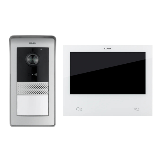
- Page 1 User Manual K40980 - K40981 IP-over-2Wires 7" Touch screen Wi-Fi one-family/two-family video door entry kit...
-
Page 2: Table Of Contents
K40980 - K40981 Index • System ....................................3 • Indoor Station ..................................4 • Functions ................................... 4 • Technical data ..................................4 • Indoor Station: views ................................. 6 • Outdoor station ................................... 8 • Functions ................................... 8 • Technical data ..................................8 •... -
Page 3: System
K40980 - K40981 System The IPo2W system allows video door entry devices to communicate with each other via the TCP/IP protocol, using a connection over non-polarised 2-wire cables. In general the IPo2W system is composed of: - Outdoor Station. Between 1 and 4 outdoor stations can be connected. Each outdoor station can be configured to communicate with up to 4 apartments. - Indoor Station. Between 1 and 4 indoor stations can be connected in an apartment. - IPo2W converter Designed to connect IP cameras to the 2-wire bus via Ethernet protocol. - System power supply unit. A single System power supply unit supports up to 4 outdoor stations, 4 indoor stations per apartment, for up to 4 apartments (a total maximum of 16 indoor stations) and 5 converters for system cameras. The IPo2W system supports the connection of up to 8 IP cameras, per individual apartment, for up to a maximum of 4 apartments. The IP cameras are connected using the apartment router via Wi-Fi or Ethernet cable and are called “apartment cameras”. Moreover, the IPo2W system supports the connection of up to 20 IP cameras via the IPo2W converters, and are called “system cameras”. The system allows up to three simultaneous calls or video previews; however, a single video stream per apartment can be shown on the monitors, while audio calls are possible on the other monitors. Please refer to "Elvox TVCC integration in IP-over-2-Wire system" document in the product page of Vimar web site to find the detailed list and the configuration parameters of compatible IP cameras. Assuming that the system power supply unit is the device at the centre of the video door entry system, indoor stations, outdoor stations and converters for cameras can be connected to the power supply unit with a star topology, a daisy-chain connection (i.e. in-out connection) or a mixed connection (star and daisy-chain). -
Page 4: Indoor Station
K40980 - K40981 Indoor Station Functions • 7" capacitive touch screen monitor • Answer video door entry calls from outdoor stations and audio intercom calls from other indoor stations or from the View Door App • Video and audio previews from outdoor stations and optional connected IP cameras • Wi-Fi connectivity • Possibility of receiving firmware upgrades via OTA (Over The Air) • Remote operation of calls via the VIEW Door App on one or more smartphones • Actuator enable/disable (powered lock and gate relay or other actuator) • Internal flash memory and micro SD card support (not included) • Automatic and manual video/image recording • Voicemail • Intercom Call between indoor stations of the same apartment and between groups of indoor stations of different apartments. • Full-duplex audio with echo cancellation and noise reduction functions • Adjustable conversation and ringtone volumes • Selectable ringtone (for outdoor station, intercom, landing) • Adjustable ringtone duration (for outdoor station, intercom, landing) • “Do not disturb” function • Connection for Landing Call button shared between the apartment group monitors • Support for call repetition from outdoor station, intercom call, landing call, call from View Door App connected to the monitor • Support for external sensors and alert management... - Page 5 K40980 - K40981 N.B.: For the “View Door” App to work correctly with the IPo2W system (the system can also operate stand-alone without the App), a suitable Internet connection must be available.
-
Page 6: Indoor Station: Views
K40980 - K40981 Indoor Station: views... - Page 7 K40980 - K40981 1 - Display 2 - Microphone Preview, answer or end call push button (backlit) 4 - Backlit alert icons a) Messages; b) Wi-Fi connection not active; c) Lock activation; d) DND (Do Not Disturb) function active; Connector for landing call button with wiring provided Connector for call repetition button with wiring provided Connector for sensor connection and alert signal management with wiring provided 8 - Lock actuation button 9 - Slot for SD card (SD card not included) N.B.: the SD card should be slotted in from the connection terminals side, making sure the terminals are facing towards the user. 10 - Speaker 11 - Connector (BUS IN; BUS OUT; DC IN – for future use)
-
Page 8: Outdoor Station
K40980 - K40981 Outdoor station Functions • Two-wire audio-video unit with wide angle lens camera • CMOS WDR video sensor with 2Mpx resolution • H.264 video compression with Full HD resolution (1920 x 1080) • 160° horizontal wide angle lens with IR-cut filter. • Full-duplex audio with echo cancellation and noise reduction functions • 2 IR LEDs for night vision • Protection degree: IP54 • Protection degree against impact: IK07 • Aluminium housing • Speaker volume adjustment • Backlit call buttons and name plates for systems with one, two or four apartments • Rainproof cover • Electric lock and relay control mounting frame • RFID reader • Acoustic signalling with tones or voice synthesis • Surface-wall mount installation • Anti-tamper function Technical data •... -
Page 9: Outdoor Station: Views
K40980 - K40981 Outdoor station: views... - Page 10 K40980 - K40981 Luminous indicators: a) Communication status indicator. Flashing green light: call in progress; continuous green light: communication in progress. Lock or relay status indicator. Green light on: lock or relay active. c) System status indicator. Continuous red light: system occupied. 2 - IR LED for night vision 3 - NFC card reader for Mifare keys art. 40169 (provided in the kit), 01598 and 01817 4 - Speaker 5, 6 - Call buttons (configurable for one-, two- or four-family building) 7 - Camera Environmental brightness sensor 9 - Microphone - Anti-vandal screw...
-
Page 11: Power Supply Unit
K40980 - K40981 Power supply unit The kit includes a DIN rail system power supply unit for installation in the control unit. Refer to the following pages for the technical characteristics. Technical Data • System power supply unit • Input: 100 – 230 VAC • Output: 32 VDC, 3.5 A max • Status LED: red indicates that the power supply unit is on • Operating temperature: from -10 °C to 40 °C • Relative operating humidity: from 0% to 90% Converter for cameras (optional device) Functions • Provides an RJ45 port for FastEthernet connection via Cat. 5e/6 cable to IP cameras directly or via a network switch Technical data: • 32V DC power supply via system bus (use the power supply unit provided in the kit) • Dimensions (mm) 32 x 92 x 22.3 • Operating temperature: from -10 °C to 40 °C • Relative operating humidity: from 0% to 90% MyVimar account is needed to use the View Door App with IPo2W devices. -
Page 12: Kit Package Contents
K40980 - K40981 Kit package contents Outdoor Station: In the single-family kits, the outdoor station is accompanied by: • 1 (one) plastic bag containing 2 (two) buttons for two-family installation. • 1 (one) plastic bag containing 2 (two) 4-pin terminals; 1 (one) connection cable for future functions; 1 (one) key compatible with the outdoor station safety screw; 4 (four) plastic wall plugs; 4 (four) metal screws. • 1 (one) plastic nag containing 7 (seven) NFC cards (1 (one) white card and 1 (one) black card for administrative uses; 5 (five) blue user cards) (the push button for single-family system is pre-installed in the outdoor station) In the two-family kits, the outdoor station is accompanied by: • 1 (one) plastic bag containing 1 (one) button for single-family installation. • 1 (one) plastic bag containing 2 (two) 4-pin terminals; 1 (one) connection cable for future functions; 1 (one) key compatible with the outdoor station safety screw; 4 (four) plastic wall plugs; 4 (four) metal screws. • 1 (one) plastic bag containing 12 (twelve) NFC cards (1 (one) white card and 1 (one) black card for administrative uses; 10 (ten) blue user cards) (the push buttons for two-family system are pre-installed in the outdoor station) Indoor Station: The indoor station is accompanied by: • 1 (one) plastic bag with 1 (one) 6-pin terminal; 2 (two) two-wired wirings; 1 (one) 12-cable wiring; 4 (four) plastic wall plugs; • 4 (four) metal screws; surface mounting bracket. Power supply unit: The power supply unit is accompanied by: • 1 (one) removable 4-pin terminal; 1 (one) terminal cover for connection to the electricity mains; 2 (two) plastic wall plugs; 2 (two) metal screws... -
Page 13: Video Door Entry System Installation
K40980 - K40981 Video door entry system installation General considerations: The procedure to follow when installing a IPo2W video door entry system is described below. Before activating the video door entry system, take care to find a suitable location for each component. What’s more, make sure you configure the dip switches of the outdoor stations first (master/slave device; assign ID, number of buttons and default actuator to activate the lock from the exit push button or from the lock release push button), see chapter entitled "Outdoor Station Configuration and Connection". 2) Make sure you connect the outdoor station and each indoor station to the system power supply unit. Connection cables that can be used: o Two-wire cable with a section of 1 or 1.5 mm : maximum distance between the power supply unit and farthest device: 150 o UTP Cat. 5e or Cat. 6 cable with 4 twisted pairs: maximum distance between the power supply unit and farthest device: 120 m. 3) Always connect every device in the system before activating the system, i.e. connect the power supply unit to the mains power. - Page 14 K40980 - K40981 Power Supply Unit Installation The power supply unit is installed by securing it to a DIN rail, and is compatible with Vimar control units. A red LED indicates when the device is operating correctly; when the LED is on, it is working normally. 40105 INPUT (L/N):~100-240V 50/60Hz 2.5A OUTPUT (+/-):32V 2.5A CONT+1A INT INT: 90s ON/180s OFF (OS) 40105 INPUT (L/N):~100-240V 50/60Hz 2.5A 40105 OUTPUT (+/-):32V 2.5A CONT+1A INT INPUT (L/N):~100-240V 50/60Hz 2.5A INT: 90s ON/180s OFF...
-
Page 15: Outdoor Station Installation
K40980 - K40981 Outdoor Station Installation The outdoor station can be installed externally on a wall surface with or without the rain guard provided. When installing the device, take care to open the front case by loosening the fixing screw on the underside of the front cover plate, using the security key provided. Fasten the base of the outdoor station, with or without rain guard, to the wall with the 4 screws and 4 wall plugs provided. We recommend fastening the device as set out below. In order to operate, the outdoor station must be connected to the system bus. The connection can be made by connecting the bus to the BUS+ and BUS- connectors. - Page 16 K40980 - K40981 102,5 43,8 95,5...
- Page 17 K40980 - K40981 7 7 , 2 2 , 2 2 ,...
- Page 18 K40980 - K40981 VIMAR V I M V I M B I A V I M R O S V I M V I M V I M B I A B I A B I A V I M...
- Page 19 K40980 - K40981 Outdoor Station Configuration and Connection In order for the outdoor station to operate, make sure you connect the bus to the BUS+ and BUS- (non-polarised) terminals. To complete the installation, note that the following can be connected: - The GND and LOCK terminals to control an electric lock 12VDC, 1.1 A peak current, 200 mA maintenance current; - The COM and NO/NC terminals to control an actuator using a relay with NO or NC contact, max 30 VDC, 6 A; The relay mode is defined by the position of the jumper on the side: - Jumper placed between the upper pair of PINs: NO (normally open) mode - Jumper placed between the lower pair of PINs: NC (normally closed) mode - The GND and EXIT terminals to connect one or more door release buttons (NO voltage-free contact). Exit Power button lock EXIT LOCK Configuration dip switch (default setting for one-family master outdoor station) Reset (Reserved) Adjustment - Volume (Potentiometer) (prog)
-
Page 20: Outdoor Station Configuration And Connection
K40980 - K40981 The basic functions of the outdoor stations can be configured with the dip switches at the top right: dip 1: Switch for setting the outdoor station as the master or slave. When set to 1 (on): the outdoor station is configured as the “master” outdoor station; in every system, only one outdoor station configured as “master” is necessary; the outdoor station supplied in the one-family and two-family kits is configured as the “master” by default. Any additional outdoor stations must be configured as "slave", with the value 0 (off). Default value: 1 dip 2-3: Pair of switches to configure the outdoor station ID; the outdoor station supplied in the one-family and two-family kits is configured as outdoor station “1” by default, by setting the dip switches to the value 00 (sw2→0, sw3→0). Any additional outdoor stations must be assigned the ID 2 (10: sw2→1, sw3→0), ID 3 (01: sw2→0, sw3→1) or ID 4 (11: sw2→1, sw3→1). Default values: 00 dip 4-5: Pair of switches to configure the use of the push buttons: the outdoor station supplied in the one-family kits is configured by default for the use of 1 (one) push button, using the value 00 (sw4→0, sw5→0); the outdoor station supplied in the two-family kits is configured by default for the use of 2 (two) push buttons, using the value 10 (sw4→1, sw5→0); for systems with 3 or 4 apartments, set the value 01 (sw4→0, sw5→1). Default values: 00 for one-family system; 10 for two-family system. dip 6: Switch to assign the activation of the lock powered or of the relay to the door release button on the front of the indoor unit and to the lock release button on the outdoor station. - Page 21 V I M V I M B I A B I A V I M V I M R O S R O S K40980 - K40981 Note that: - For one-family outdoor stations, the call button corresponds to apartment 1. For two-family outdoor stations, the lower call button corresponds to apartment 1, whereas the upper call button corresponds to apartment 2. - For four-family systems, the push button mapping is according to the following scheme: For the configuration of the number of each apartment, please refer to the paragraph entitled “Indoor Station Configuration". Reset push button: The reset push button performs a factory reset of the outdoor station, i.e. it returns the outdoor station back to its original factory setting.
-
Page 22: Configuring The Administration Keys
K40980 - K40981 Configuring the administration keys With the front not installed, quickly press the reset button on the outdoor station twice: the device will respond with a sequence of 4 beeps. The configuration procedure begins from this moment and is signalled by the slow flashing of the name plate backlighting LEDs; any previous configurations are deleted. Alternatively, you can launch the configuration procedure from the administration menu of an indoor station, see "Installer settings": in this case, any previous key configuration (administrator and user) will not be deleted until you proceed to the next step 2. In this case too, the key programming status is signalled by the slow flashing of the backlighting LEDs, and it lasts about 30 s. 2) Bring the first key up to the RFID reader; the device will emit a long beep; the first key is configured as “administration key for addition”. We recommend marking the key with “key for addition” 3) Bring the second key up to the RFID reader; the device will emit a long beep; the second key is configured as “administration key for removal”. We recommend marking the key with “key for removal”. The administration keys and all user keys can be reset by repeating the above procedure from the beginning. 4) If no other action is carried out, the registration procedure will end after 30 seconds with a warning tone (4 beeps). Any new configuration of the administrator keys and user keys will be possible, repeating the above procedure from the beginning. The front case can now be installed on the outdoor station, taking care to close the anti-tamper key. Adding a user key For the addition and removal of user keys, the front of the outdoor station does not necessarily have to be opened. These operations can also be carried out after the first-time system installation. 1) Bring the “administration key for addition” up to the RFID reader: the device will beep and start to flash slowly. 2) Bring an unprogrammed key up to the reader. The device will enable it as a “user key”. The device will beep when the configuration is complete. 3) Repeat step 2) to add any other keys. 4) The procedure for enabling user keys will terminate after about 5s of inactivity. The device will beep 4 times and stop flashing to indicate the end of the procedure. The keys added using this procedure will immediately be available for the activation of locks, as specified below. Removing user keys A user key can only be removed using the actual key itself, as specified below. -
Page 23: Lock1 Lock Activation
K40980 - K40981 Powered lock activation (Lock1) Bring a user key up to the RFID reader for less than 2s: the lock will be activated after one beep. Relay activation (Lock2) Bring a user key up to the RFID reader for longer than 2s: the relay will be activated after an initial notification beep followed by a confirmation beep. -
Page 24: Indoor Station Installation
K40980 - K40981 Indoor Station Installation The indoor station can be installed on a wall surface. Note that the indoor station is supplied complete with a bracket that is compatible with flush mounting boxes: - Mounting box 7249 (with bracket 40196) - Round mounting box 2M V71701 - Horizontal/vertical mounting box 3M V71703, V71303 - British Standard square mounting box Use the screws and wall plugs provided in the kit to install the bracket on the wall. In order to operate, the indoor station must be connected to the system bus. The connection to the system bus must be made either directly via the power supply unit bus or via the bus of another indoor station. 184,3 155,2 25,3 24,5... - Page 25 K40980 - K40981 8 3 , 8 3 , 8 3 ,...
- Page 26 K40980 - K40981 BUS IN BUS IN BUS OUT BUS OUT DC IN...
- Page 27 K40980 - K40981...
-
Page 28: Indoor Station Connection
K40980 - K40981 Indoor Station Connection In order to operate, the indoor station must be connected to the system bus. The connection to the system bus must be made either directly via the power supply unit bus or via the bus of another indoor station. LC-GND: connection for landing call button on voltage-free contact, max distance 10 m BUS IN-BUS IN: BUS input BUS IN BUS IN BUS OUT BUS OUT-BUS OUT: BUS output Terminals for sensor connection BUS OUT DC IN DC IN-GND: (Reserved) NO-COM: normally open relay, for connection to call repetition (max 30 VDC, max distance 10 m) -
Page 29: Indoor Station Configuration
K40980 - K40981 Indoor Station Configuration The indoor stations can only be configured after all the system devices have been installed and connected, and after the outdoor stations have been configured. In each apartment, only one “master” (main) indoor station should be defined, which can link up to the cloud services via the apartment’s Wi-Fi network; up to three other “slave” (additional) indoor stations may be configured, with more restricted functions. To configure the indoor station, power up the video door entry system. The indoor stations will take a few tens of seconds to activate. Begin the indoor station configuration procedure with the "Master” indoor station of the first apartment. Once it is active and ready for configuration, the following screen will appear on the indoor station in order to choose the language: Ελληνικά Nederlands English Italiano Français Figure 11 1) Choose the language you intend to use when configuring and using the device: tap on your chosen language and tap the tick at the bottom right (Fig. 11). The same language will be used for the outdoor station voice messages, where enabled. user Figure 12... - Page 30 K40980 - K40981 2) The screen shown above then appears (Fig. 12). Enter the following in order: a) User name. In an apartment with several devices, this name distinguishes each indoor station from the others. Within a multi-apartment system, the group relating to each apartment is identified by the user name of the “master” device in the respective apartment. We therefore suggest you enter a significant user name, such as “Smith family” for the master of a multi-family system, "entrance" or "second floor" for the slaves or for a single-family system. Apartment number. Corresponds to the outdoor station call buttons. c) Extension number, i.e. the number that identifies the indoor station being configured. The master indoor station of each apartment must be identified with the number “1”. Any additional (slave) indoor stations will unequivocally be identified with the numbers "2", "3", "4". Apartment 1 Apartment 2 Apartment 3 Apartment 4 Name: Jones Name: Taylor Name: Williams Name: Wilson Apartment: 1 Apartment: 2 Apartment: 3 Apartment: 4 Extension:1 (Master) Extension:1 (Master) Extension:1 (Master) Extension:1 (Master) Name: Entrance Name: Living room Name: Living room Name: Entrance Apartment: 1 Apartment: 2 Apartment: 3...
- Page 31 K40980 - K40981 In the case of subsequent device configuration, the date, time and time zone will be set automatically as in the first indoor station configured. Figure 13 3) Select the time zone as shown in Fig. 13. Note that you can tap the bottom left arrow to return to the previous page, if necessary. After selecting the time zone, tap the tick at the bottom right. Figure 14...
- Page 32 K40980 - K40981 4) The indoor station identified as the apartment “master” will prompt you to configure the date and time. After entering the information, tap the tick on the right. Figure 15 5) The system will start the configuration phase, as shown above in Fig. 15. If the system recognises that more than one device within the same apartment have the same identification number (same extension number), the indoor station will show the page in Fig. 16. If the system confirms that each indoor station within the same apartment has its own unique identification number (extension number), the indoor station is fully configured and the configuration successful page will appear on the indoor station, as shown in Fig. 18 (successful!). Figure 16...
- Page 33 K40980 - K40981 6) Configuration completed successfully. Figure 18 When the configuration is complete, the indoor station will reboot as shown above. You can now proceed with configuration of the next indoor station. After rebooting (which takes a few tens of seconds), the home page will appear on the indoor station as shown in the page below: Figure 19...
-
Page 34: Indoor Station: Home Page
K40980 - K40981 Indoor Station: Home page Icons of Status icons the sensor activation modes Primary Date and time functions Secondary functions Figure 20 The indoor station home page is organised to provide the most important information for using the video door entry device and accessing the various functions. Status icon (area encircled in yellow) Master entrance panel status: the icon indicates that the master entrance panel is unreachable, so the system cannot operate correctly (this malfunctioning is also signalled by the flashing of all the monitor icons) Speaker status: the speaker is muted in this case SD card status: this icon indicates that an SD card is inserted in the slot or not (shown with an “x”) Cloud connection status: this icon indicates whether the cloud connection is active correctly (for the master monitor of each apartment only, once the Wi-Fi has been configured correctly) -
Page 35: Primary Functions (Area Encircled In Blue)
K40980 - K40981 Primary functions (area encircled in blue) Video preview from outdoor stations Contacts List Consult list of calls Consult list of recordings Secondary functions (area encircled in white) Icon to activate/deactivate the DND (Do Not Disturb) function. Note that once the DND function is activated, it mutes the video entryphone for the whole day by default. It is possible to set a daily time slot during which the DND function is active (the DND function is deactivated by default). Icon to activate/deactivate the automatic recording of the photo or video of the caller for each call from an outdoor station. Icon to call all mobile phones connected to the indoor station via the View Door App. Icon to activate/deactivate the voice message service. When activated, a call from the outdoor station will be followed by a predefined or custom audio message. The guest can leave an audio message (the voice message service is deactivated by default). Icon to access the device or video door entry system settings. -
Page 36: Icons Of Sensor Activation Modes (Area Encircled In Green)
K40980 - K40981 Icons of sensor activation modes (Area encircled in green) “At home” icon “Away” icon, “Night” icon “Custom” icon For further details, please refer to the “Sensors” chapter of this manual below. -
Page 37: Call From An Outdoor Station
K40980 - K40981 Calls from an outdoor station On receipt of a call from an outdoor station, the following screen appears: 16:15:58 Door Panel 1 21-11-2017 Figure 21A The screen shows the footage from the calling outdoor station, whose name is indicated in the top left corner. There is a row of touch controls along the bottom. Note that the row of controls is hidden automatically; just tap the display to make it reappear. The icons on the bottom bar have the following functions: Take a photo of the screen contents; Make a video recording (with a minimum duration of about 15s) of the screen contents; Adjust the audio volume of the speaker as shown in the figure below: (copy fig. 22); Answer the call, alternatively you can answer by pressing the backlit preview button: During a conversation, the icon shows the monitor microphone is active: Press it to mute the microphone: End the call and go back to the home page; the call can also be ended by pressing the preview button. - Page 38 K40980 - K40981 Consult the video from the other outdoor stations present (the audio conversation remains active with the calling outdoor station); Consult the video from the IP cameras present (the audio conversation remains active with the calling outdoor station); Activate the locks connected to the outdoor station displayed If several monitors are present in the same apartment, when a call arrives from an outdoor station all the monitors will play the call tone with the preview and lock release icons flashing; only the main monitor will show the video preview (as a general rule, the screen can only be kept active in just one monitor per apartments). The preview can also be activated on the slave monitors by tapping the screen or preview icon; in this case the screen on the previously active monitor will switch off.
-
Page 39: Simultaneous Calls From Another Outdoor Station
K40980 - K40981 Simultaneous calls from another outdoor station If a call from a second outdoor station arrives at a monitor already in a conversation, a warning window appears: Figure 21B The warning window can be removed by clicking on the red push button. Once the first call has ended using the preview icon or the red handset in the bar at the bottom, the second call will also end if it was not answered by another monitor: this way, the video preview can be activated followed by an audio conversation with the second calling outdoor station.” Specify which icons must be pressed to activate video and audio in sequence. Any other monitors in the same apartment will signal the second simultaneous call with the call tone and the flashing icons; the video preview can be activated by tapping the screen or the preview icon, so you will be able to answer the second call simultaneously. The moment the video streaming is activated on a second monitor in the same apartment, the screen on the monitor already in a conversation will switch off but the voice call will remain active, as signalled by the preview LED which will start to flash slowly. Tap the screen again to reactivate the video stream and stop the flashing, while at the same time deactivating the active video stream in the other apartment monitor. -
Page 40: Primary Functions: Details
K40980 - K40981 Primarry functions: details Consult Outdoor Stations: tap this icon to consult the master outdoor station in preview mode. The preview page is similar to the call page. By default, the microphone is muted on activation of the preview but it can be activated by tapping the related icon. Unlike the incoming call case, if the video source changes, the audio played comes from the outdoor station or (where available) from the IP camera displayed. Consult Contacts: this page lists the indoor stations available for intercom calls, and the favourite cameras for video preview. Figure 22A In general, the indoor stations in an IPo2W system offer an intercom function: o Between devices in the same apartment o Between devices in different apartments Intercom calls can be made by selecting one of the contacts. Devices in the same apartment are identified by an icon with a star and the device name. Devices in a second apartment, if there is one, are only shown as an apartment group, and are identified by an icon without a star and with the name of the master device in the second apartment. In a recently configured IPo2W system composed of multiple indoor stations, all devices can communicate with the other indoor stations by default (regardless of whether they are in the same apartment or a different one). To make an intercom call to a contact, tap the icon corresponding to the contact concerned. The monitor called will show the following screen:... - Page 41 K40980 - K40981 Figure 22B With the icons to adjust the speaker volume answer, refuse the call, mute the ringtone. Once you have accepted the call, the icons for adjusting the volume of the speaker, ending the call and muting your microphone will be available. Intercom calls can always be interrupted by calls made from outdoor stations. To remove a contact, just touch the related icon for a long time; a window will appear to prompt you to confirm that you want to remove the contact concerned. Note that the indoor station intercom function is available between users that have each other among their contacts. If a user wants to prevent communication with a specific user, they just have to remove the unwanted user from their contacts using the menu that can be opened with the icon at the top right. This will access a contact addition or removal menu, for both intercom calls and favourite IP cameras. By default, the system contacts can all be enabled, whereas all the cameras are disabled. Figure 22C Removing the contact the will prevent calls between the two users, in either direction. The contacts removed relating to other apartments will no longer be visible in the Consult Contacts page; the contacts removed relating to their apartment will remain visible, with a prohibition symbol across them.
- Page 42 K40980 - K40981 Consult list of calls Tap the “Calls” icon to open the list of calls in chronological order. Each call is identified by a line containing the following in order: an icon that identifies whether the call was incoming or outgoing, and if the call was answered or not; name of the device from which the call was made; the date and time of the call; link to a photo/video/audio message, if available. Figure 23 Messages can be deleted by touching the call line for a long time and selecting the remove option.
- Page 43 K40980 - K40981 Consult list of recordings Tap the “Recordings” icon to open the list of recordings (in picture or video format) in chronological order. Each recording is identified by a line containing the following information: Figure 24 Icon of the device from which the pictures were taken; the device identification; the date and time at which the recording was made. Recordings can be deleted with the “bin” icon at the bottom right of the page. Note: if the “Auto delete” function is active, it deletes all recordings made more the 30 days ago. What’s more, when the maximum memory capacity is exceeded, the oldest recordings are automatically deleted. Recordings should be saved directly to the SD card, where present, thereby expanding the device memory capacity. Prolonged tapping on a recording will open a window with the following functions: - Removal of the individual recording - Removal of all the recordings - Copy of any recordings saved in the device’s internal memory onto an SD card...
-
Page 44: Secondary Functions: Details
K40980 - K40981 Secondary functions: details Icon to activate/deactivate the DND (Do Not Disturb) function; tap this icon to activate/deactivate the DND function. Icon to activate/deactivate the automatic recording of the photo or video of the caller for each call from the outdoor station. Icon to call all mobile phones connected to the indoor station. Icon to activate/deactivate the voice message service Icon to access the device/system settings Tap the “Settings” icon to access the settings menu shown in the following figure. - Page 45 K40980 - K40981 The meaning of each icon in the menu is explained below: Grants access to the “General Settings” sub-menu The functions that can be consulted and configured via the “General Settings” sub-menu are listed below; the functions appear in two different pages: Figure 26 Figure 27...
- Page 46 K40980 - K40981 • System Info: page containing the main information about the indoor station, including the firmware version, apartment number and extension number (Fig. 28). Figure 28 • Language: page for configuring the user language of the indoor station. Ελληνικά Nederlands English Italiano Français Figure 29 • Date Format Setting: page for configuring the date format. Figure 30...
- Page 47 K40980 - K40981 • Clean Mode: page for activating the device cleaning mode (we recommend activating this mode before cleaning the device to avoid setting functions accidentally). Figure 31 • Backlight Settings: page for activating/deactivating the button backlighting. This page can also be used to configure the time-out of the indoor station display. Figure 32 • Terminate call when unlocking: this function allows to end the call automatically during the ringing phase only, by pressing the “lock” button. In preview or communication mode, this function is not available.
- Page 48 K40980 - K40981 • User Reset: page containing the following options: a) Reset the user settings b) Restart the device c) Format the SD card Note: it will not be possible to receive and answer calls while the device is restarting. Figure 33 • Voice message: page for configuring a voice message that the outdoor station will play following a call. As shown in the figure below, firstly the audio playback mode can be configured; secondly, you can record your own voice message. Figure 34...
- Page 49 K40980 - K40981 a) Voice message playback mode Figure 35 b) Record audio message Figure 36 • Customized Background: page for configuring the background picture for the home page. Please bear in mind that very pale backgrounds could compromise the readability of texts and graphic elements on the monitor.
- Page 50 K40980 - K40981 Opens the ringtone configuration page Figure 37 Figure 38 • Beep sound: activates/deactivates an acoustic signal on every key press • Ringtone-volume: page for configuring the call ringtone Figure 39...
- Page 51 K40980 - K40981 • Talk volume: page for configuring the audio communication volume Figure 40 • Entry panel ringtone: page for choosing the ringtone for calls from the outdoor station Figure 41 • Intercom ringtone: page for choosing the ringtone for calls from the indoor station Figure 42...
- Page 52 K40980 - K40981 • Landing call ringtone: page for choosing the ringtone for calls from the landing push button Figure 43 • Ring time: page to configure the ringtone duration for calls from the following, respectively: - Outdoor Station - Intercom - Landing Push Button Regardless of the ringtone duration, you have 45 seconds to answer calls. Figure 44...
- Page 53 K40980 - K40981 Opens, first of all, the DND (Do Not Disturb) function activation page Figure 45 It is then possible to set the daily time slot for the DND function (the time slot is the whole day by default). Figure 46...
- Page 54 K40980 - K40981 Opens the Wi-Fi configuration page. Connecting the Indoor Station to a Wi-Fi network allows you to: - Connect and see a video preview from the apartment cameras connected via a Wi-Fi router; - Connect the video door entry system to one or more smartphones via the “View Door” App (only available for the master monitors of each apartment) - Receive any fw updates for the Indoor Station and Outdoor Station (only available for the master monitors of each apartment) The availability of fw updates is automatically checked by the system and signalled by a notification dot on the “Settings” icon on the home page and the related sub-icons leading up to the fw update icon. N.B.: In order to ensure the IPo2W system is in the best operating and security conditions, we recommend installing any updates. The first page shows the functions for connecting the indoor station to the Wi-Fi, configuring the call forwarding service to the App, removing connected Apps and resetting the Wi-Fi factory setting. Figure 47 The second page shows the QR code to find the App in the Android and iOS stores, and the QR code to connect the indoor station to the App.
- Page 55 K40980 - K40981 Info: The procedure for Indoor Station configuration via App, using the “pairing” QR-Code is explained in detail in the chapter entitled "App: Configuration” below. Figure 48...
- Page 56 K40980 - K40981 In detail: • Wi-Fi Configuration: page for connecting the monitor to the Wi-Fi network for access to the cloud (only master apartment monitors) and consulting the apartment cameras. Access credentials will be required for the network which must automatically assign an IPv4 address via DHCP server (for compatibility with the wired network routing scheme, addresses in the 10.0.0.0-10.255.255.255 range cannot be assigned). Figure 49 • Call forwarding delay: page for configuring the call forwarding delay from the indoor station to the App. Figure 50...
- Page 57 K40980 - K40981 • Remove connected Apps: page for removing accounts to which the indoor station is connected Figure 51 • Wi-Fi factory settings: page for resetting the Wi-Fi Figure 52...
- Page 58 K40980 - K40981 Opens the configuration page for the IP cameras connect to your router via Wi-Fi network or Ethernet cable. Esempio di collegamento con telecamere IP Elvox Connection example with Elvox IP cameras View Door Router Targa esterna Monitor Entrance panel Cloud 100-240 V~ Convertitore Converter Alimentatore Power supply unit Switch (Optional) Telecamere IP Elvox di sistema compatibili Telecamere Elvox di appartamento compatibili Compatible system Elvox IP cameras Compatible Elvox cameras for apartments 2 Wire Necessario per collegare più telecamere allo stesso convertitore Cat 5...
- Page 59 K40980 - K40981 Tap the “+” icon to add an apartment IP camera to a master monitor Figure 53 Be sure to fill in the fields in the next page: Figure 54 The IPo2W video door entry system can be interfaced with certain IP cameras. The above page allows the configuration of apartment IP cameras to the video door entry system. The list of compatible cameras is available in the product page of the IPo2W video door entry kits, on the Vimar company website. The use of other cameras is not guaranteed and lies under the sole responsibility of the user. For correct operation, the Elvox IP camera must belong to the same IP network as the indoor station concerned and must have a fixed IP address (static and reserved by the DHCP server) so that the IP address uniquely identifies the camera in the IP network. The configuration of an apartment IP camera entails the compilation of the fields shown on the page indicated. To proceed with configuration, you need to know the IP address and the access credentials of the cameras concerned. To facilitate configuration, in master indoor stations, the “lens” icon can be used to perform an automatic search for the IP cameras connected to the apartment network.
- Page 60 K40980 - K40981 From the list of devices found during the automatic search, take care to: 1) Consider the addresses relating to the cameras declared to be compatible; 2) Enter the configuration page by tapping the corresponding IP address 3) Check the required fields are compiled, i.e.: - Label indicating the identification you wish to give the camera - IP address of the camera - Credentials for consulting the camera (username and password) - Appropriate video streaming. For IP cameras a video stream coded H.264 is required; we recommend you select "minor stream". Beware that a camera with high resolution and bitrate (for instance 1920x1080 at 3072 kb/s) could make consulting from a monitor or App complicated, especially with low-performing Wi-Fi connections. If you are having problems, we suggest you reduce the resolution and the bitrate until the view is satisfactory. For further details please consult the camera documentation. Any slave monitors automatically inherit the camera configuration of the related master monitor and apartment cameras can only be added from the master monitor. To consult cameras, the slave monitors must be connected to the same Wi-Fi network as the master. A similar procedure can be followed to connect system cameras, see "System cameras" paragraph on the following pages for details. Please refer to "Elvox TVCC integration in IP-over-2-Wire system" document in the product page of Vimar web site to find the detailed list and the configuration parameters of compatible IP cameras.
- Page 61 K40980 - K40981 Opens the system configuration sub-menu. This sub-menu is password-protected. The default password to access system configuration is “0000”. To keep the system settings confidential, we recommend customising the password and noting it down in a secure place or remembering it. The functions that can be consulted and configured via the “Installer Settings” sub-menu are listed below: Figure 55 • Monitor Settings: page for configuring the indoor station Figure 56...
- Page 62 K40980 - K40981 The “Monitor Settings” page will grant access to the following pages: • Software Update: page for the fw update of the indoor station Figure 57 Address Settings: page for configuring the indoor station address: • user Figure 58 • Password Settings: pages for updating the installer’s password Figure 59...
- Page 63 K40980 - K40981 • Factory Reset: page for resetting the indoor station (the reset will reset the indoor station to the original factory settings): Figure 60 Note: if it is necessary to perform a factory reset on the entire video door entry system, we recommend the following procedure: 1) Perform a factory reset of the slave monitors 2) Perform a factory reset of the master monitors 3) Update the dip switch configuration if necessary 4) Perform an ordered Factory Reset of the outdoor stations, from the entrance panel with ID “1” onwards. 5) Wait 1 minute • Backup/restore Settings: page for saving and restoring the settings of the indoor station on the SD card inserted in the monitor concerned. The indoor station configurations (e.g.: ringtone, volume, ...) are saved in particular. • Time Settings: page for configuring the system date and time Figure 61...
- Page 64 K40980 - K40981 • Timezone: page for configuring the time zone Figure 62 • Door Panel Settings: page for configuring the outdoor station Figure 63A Figure 63B...
- Page 65 K40980 - K40981 The “Door Panel Settings” page will grant access to the following pages: • Software Update: page for verifying the firmware version installed in the outdoor station and managing updates. Figure 64 The fw update of the outdoor station can be carried out on this page, where available. When the update procedure is launched, all the LEDs on the monitor flash; we recommend you wait for it to be completed before proceeding with the same operation on another device. • Tamper Switch Enable: page for enabling the anti-tamper sensor in the outdoor station Figure 65...
- Page 66 K40980 - K40981 • Vocal Message Settings: page for activating/deactivating vocal message or acoustic feedback Figure 66 Figure 67...
- Page 67 K40980 - K40981 • Vocal Message Volume: page for configuring the volume of vocal messages Figure 68 Figure 69...
- Page 68 K40980 - K40981 • Lock Settings: page for configuring the outdoor station actuators Lock1: electric lock. The configurable time is for the maintenance current duration (200mA). Lock2: relay. The configurable time is for the activation duration. Exit button: external push button to release the default lock. The configurable time is related to the delay between pressing the external push button and the activation of the default lock. Figure 70 • Backup/restore settings: page for saving the outdoor station settings on the SD card inserted in the monitor, and for restoring them; in particular outdoor station 1 contains information about the system devices (outdoor stations, indoor stations, system cameras and RFID keys), so we recommend you back up the settings and keep the related files for any future maintenance work Figure 72...
- Page 69 K40980 - K40981 • System cameras: page for configuring the system IP cameras: the procedure is similar to the one described earlier for IP apartment cameras, a static IP address in the range of 10.128.xxx.yyy with netmask 255.0.0.0 must be assigned to the IP cameras; The system cameras, unlike the apartment Wi-Fi cameras, can be added from any monitor in the system (master or slave). Esempio di collegamento con telecamere IP Elvox Connection example with Elvox IP cameras View Door Router Targa esterna Monitor Entrance panel Cloud 100-240 V~ Convertitore Converter Alimentatore Power supply unit Switch (Optional) Telecamere IP Elvox di sistema compatibili Telecamere Elvox di appartamento compatibili Compatible system Elvox IP cameras Compatible Elvox cameras for apartments 2 Wire Necessario per collegare più telecamere allo stesso convertitore...
- Page 70 K40980 - K40981 Figure 73 In addition, for system cameras, access can be restricted to certain specific apartments by accessing the specific configuration menu and scrolling on the second page: Figure 74 Please refer to "Elvox TVCC integration in IP-over-2-Wire system" document in the product page of Vimar web site to find the detailed list and the configuration parameters of compatible IP cameras.
- Page 71 K40980 - K40981 • Administrator RFID keys: page for launching the configuration procedure for the specific entrance panel RFID keys (see chapter entitled " Configuring the administration keys"). Figure 75 • PLC: page with operating parameter values in the PLC module Note: correct device operation usually requires a AGC value between -20 and +20. Values outside this range may indicate issues with the system wiring. Figure 76...
-
Page 72: Sensors
K40980 - K40981 Sensors After a firmware update, the monitor is set up for connection with up to 8 sensors and notification of the related activations via an alert tone, notification on the View Door App (where configured) and activation of an external signalling (where set up). The related configurations are inside the Settings menu → Password-protected sensors (default: 9999). Figure 80 Figure 81... -
Page 73: Connections
K40980 - K40981 Connections Sensor max 10 m 860A Additional ringtone Network 0170/101 Relay Ringtone Ringtone power supply > 30 V Figure 82 The IN1-IN8 sensor inputs of the monitor must be connected to SELV voltage-free contacts; the closing of connections is on the GND contact. The NO, COM and 12V contacts can be used to activate an external signalling: if a sensor is activated, the NO and COM contacts close (max 30 V 2 A), and the 12V contact provides a 12V DC max 500 mA power supply referring to GND. The maximum wiring length is 10 m for each contact. -
Page 74: Configuration
K40980 - K40981 Configuration Open the “Sensors” menu: Figure 83 Perform the “Sensor configuration”: Figure 84 For each sensor, the following parameters can be specified: Figure 85... - Page 75 K40980 - K40981 Parameter Possible values Name of sensor Free text Identifies the sensor in the activation menus and in the alert messages Type of sensor Free text: Identifies the type of sensor in the alert messages "Gas", "smoke", "water", "magnetic", "PIR move- ment", "custom" Activation type Immediate Once enabled from a specific mode, the sensor is immediately in a position to trigger the alert signal Delayed Once enabled from a specific mode, the sensor will be able to trigger the alert signal after the amount of time defined by the “Activation delay” parameter; an acoustic tone will signal the delay time Alert delay 1-99 seconds Delay between the activation of an enabled sensor and the activation of the alert signal Activation delay 1-99 seconds Delay between the enabling and the actual activation of a sensor NO-NC Normally open sensor Normally closed sensor Once sensor configuration is complete, the enabling modes are defined in the “Sensor mode” menu. If the settings of a sensor need to be modified, make sure you select a mode in which the sensor is disabled, or disable the sensor from active mode temporarily. Four modes are available: “At home”, “Away”, “Night”, “Custom”; in each one, the sensors to be activated must be selected. For instance, in the following figure the “Custom” mode envisages the enabling of sensors Sensor1, Sensor2 and Sensor7: Figure 86 The selection of each mode, and therefore the activation of the related sensors, is carried out from the device home page (the insertion of a password of the sensors menu is required by default):...
- Page 76 K40980 - K40981 Sensor Figure 88 The mode change is signalled by a warning tone. In the “Siren duration” menu, you can configure the duration, tone and volume of the alert signal (“siren”). What’s more, the volume of the mode change tone can be configured. In the “Sensors events” menu, you can consult the list of events recorded by the monitor: Figure 89 The events are also notified and included on the “Messages” pages of the View Door App: Figure 90 Figure 91 The “Sensors password” menu allows you to change the default password for managing the sensors and modes. What’s more, you can disable the password request to change the alert mode. The “Factory configuration” menu allows you to restore the Sensors section to its default configuration.
- Page 77 K40980 - K40981 Information After a firmware update, the Settings menu contains an “Info” page listing the main new features of the firmware version installed for the user. Immediately after the update, the page icon and the Settings icon on the home page present a warning badge, which disappears after the first-time access to the Info page.
-
Page 78: App: Configuration
K40980 - K40981 App: Configuration 1) In order to be connected to the View Door App, the device requires a MyVimar account. If the account is not available, create one at the link: https://www.vimar.com/en/int/user/login (the account can be created both on the web and using the App, as explained further below). 2) Check that your monitor is connected to the Internet. 3) Start the App; if no other devices have been previously configured using your MyVimar account, the App will show the page displayed below; otherwise, to add a new device click on the "+" icon at the top right of the "Devices" page and go to point 7. The App will display the page shown below (Fig. 101): Figure 101... - Page 79 K40980 - K40981 4) Tap on “Login”: the page shown in Fig will be displayed. 102. Figure 102 5) Tap on the bottom (Go to MyVimar login) to go to the account login page Fig. 103. If you do not have a MyVimar account yet, create it by tapping the link “Want to create a profile? Do you want to manage your profile?” which takes you to the MyVimar website. Figure 103...
- Page 80 K40980 - K40981 6) Once you have logged into your account, the “Devices” page is displayed, as shown in Fig. 104: Figure 104 7) To connect the device, touch the central “+” icon to open the page shown in Fig. 105. As can be seen in the image, the camera has been activated; frame the QR code with the box shown by the App. in the QR code can be found on the indoor station, at this path: display > Settings > Wi-Fi (second page of the pager, see figure 48). Figure 105...
- Page 81 K40980 - K40981 Scan the QR Code, the App will recognise the code and the page shown in Fig will be displayed. 106 Figure 106 As soon as the App has identified the device via the cloud, it will prompt you to confirm that you want to add the device to the “devices” connected to the App. Figure 107...
- Page 82 K40980 - K40981 10) The App will then prompt you for the device a name; this name will identify the device among the other “devices” on the App. Figure 108 11) Tap “Save” to confirm that you want to connect the device to the App. For security, the App will then prompt you to enter a numerical password for the device, as shown in the following figure. Note: we recommend remembering the newly set device password. Should you wish to share the device with another user, they will have to use the same password. Figure 109...
- Page 83 K40980 - K40981 12) Once the “device password” has been confirmed, the new device will appear in the list of “devices” connected to the App. Door Panel 1 17:52:45 23.10.2022 Figure 110 13) Tap the three dots at the top right of the connected device page to open the window shown in the image below: Door Panel 1 17:52:45 23.10.2022 Figure 111...
- Page 84 K40980 - K40981 14) The window offers two options: a. Setting: opens the device configurations available on the App. b. Share: the first user to configure the device can manage or administer the device and share it with other users for use and consultation, provided they have a MyVimar account. To share the device, enter the email address that the user has linked to the MyVimar account. Tap the “Setting” option to open the “Device settings” page shown in the figure below. Figure 112 As can be seen in the figure above, the page offers the following options: a) Modify device name: tap this to open a window in which you can edit the device name. b) Device details Figure 113...
- Page 85 K40980 - K40981 Note: if a fw update is available, a coloured symbol will appear next the fw version. The update should be activated from the dedicated monitor menu. c) Share device Figure 114 The first user to configure the device can manage or administer the device and share it with other users for use and consultation, provided they have a MyVimar account. To share the device, enter the email address that the user has linked to the MyVimar account.
- Page 86 K40980 - K40981 d) Push notification settings As shown in the image below, the following alerts can be activated: o Call alerts o Tamper alerts o Notifications due to alert sensor activation. Receiving notifications requires certain permissions in the device settings; these permissions vary according to the model and operating system. Check the notification settings on your device in detail. Figure 115...
- Page 87 K40980 - K40981 e) Advanced settings Figure 116A As shown in the image below, the following options are available: o Modify device password o Activate/deactivate shortcut icons o Activate/deactivate thumbnails o Configure the preview/conversation time limit o Create icons for rapid lock activations on the home page of your phone. Figure 116B...
- Page 88 K40980 - K40981 Figure 116C f) Remove the device from the App Tap “Delete” to remove the device from the App.
-
Page 89: App: Use
K40980 - K40981 App: use You can consult the device connected to the App from the “Devices” section Door Panel 1 17:52:45 23.10.2022 Figure 117 Tap the image of the device to activate the preview, as shown in the image below: Door Panel 1 19:30:24 23.10.2022 Figure 118... - Page 90 K40980 - K40981 As can be seen in the previous image, the following functions are available during the preview: time-line icon: consults the recording of call from the outdoor station audio communication icon: activates communication with the outdoor station lock icon: activates the lock (electric lock or relay)
-
Page 91: Integration With Voice Assistants
K40980 - K40981 Integration with voice assistants IPo2W devices can interact with the Amazon Alexa and Google Assistant voice assistants. Amazon Alexa To activate the integration, simply activate the “Vimar View Door” skill from the Amazon Alexa App and link with your MyVimar account. The skill will allow you to receive call alerts from an outdoor station in the Echo family of devices. Audio-video interaction will be possible in Echo Show devices. Only audio interaction will be possible in the Echo, Echo Flex, Echo dot, Echo Studio devices. Amazon, Alexa and all related logos are trademarks of Amazon.com, Inc. or its affiliates. If you activate the Vimar View Door skill, you will also be able to control two locks (powered lock and relay). Please note that lock enabling via the Amazon Alexa App should be carried out by the end user. The vocal control of a lock, for safety reasons, is protected by a 4-digit safety PIN. Please keep this code confidential, to avoid unauthorised people activating it. We specifically advise against using the vocal release control during communication with the outdoor station, since the code may be heard outside. -
Page 92: Wiring Diagrams
K40980 - K40981 Wiring diagrams K40980 (one-family) • Maximum distance from the power supply unit to the outdoor station: - 150 m (with two-wire cable, preferably twisted with section 1 or 1.5 mm - 120 m (with UTP Cat. 5e or Cat. 6 cable with 4 twisted pairs). •... - Page 93 K40980 - K40981 Wiring diagrams K40981 (two-family) • Maximum distance from the power supply unit to the outdoor station: - 150 m (with two-wire cable, preferably twisted with section 1 or 1.5 mm - 120 m (with UTP Cat. 5e or Cat. 6 cable with 4 twisted pairs). •...
- Page 94 K40980 - K40981 Wiring diagrams (Connection of a four-family system with up to 4 indoor stations per apartment) • Maximum distance from the power supply unit to the outdoor station: - 150 m (with two-wire cable, preferably twisted with section 1 or 1.5 mm A1.1 BUS IN...
- Page 95 K40980 - K40981 Wiring diagrams • Variant of a system connection with several outdoor stations (up to 4) • Maximum distance from the power supply unit to the outdoor station: - 150 m (with two-wire cable, preferably twisted with section 1 or 1.5 mm - 120 m (with UTP Cat.
- Page 96 Note: all IP system cameras must have IP address 10.128.xxx.yyy with netmask 255.0.0.0. Please refer to "Elvox TVCC integration in IP-over-2-Wire system" document in the product page of Vimar web site to find the detailed list and the configuration parameters of compatible IP cameras.
- Page 97 K40980 - K40981 Wiring diagrams • R elay connection variant with NO/NC contact of the outdoor station, to activate an auxiliary service Auxiliary service power supply unit GND EXIT GND LOCK BUS+ BUS- COM NO/NC Auxiliary service (max 30 VDC, 6A)
- Page 98 As an alternative to independent management, you can deliver the equipment you want to dispose of free of charge to the distributor when purchasing a new appliance of an equivalent type. You can also deliver electronic products to be disposed of that are smaller than 25 cm for free, with no obligation to purchase, to electronics distributors with a sales area of at least 400 m . Proper sorted waste collection for subsequent recycling, processing and environmentally conscious disposal of the old equipment helps to prevent any possible negative impact on the environment and human health while promoting the practice of reusing and/or recycling materials used in manufacture. • For further information, visit www.vimar.com...
- Page 99 K40980 - K40981...
- Page 100 Viale Vicenza 14 36063 Marostica VI - Italy www.vimar.com 49401884B0_MU_EN_IPo2W_K40980_K40981 05 2307...
Need help?
Do you have a question about the Elvox K40980 and is the answer not in the manual?
Questions and answers