
Related Manuals for National Instruments NI 4472


Summary of Contents for National Instruments NI 4472
- Page 1 NI 4472 User Manual Dynamic Signal Acquisition Device for PCI and PXI /CompactPCI ™ NI 4472 User Manual May 2001 Edition Part Number 322940B-01...
- Page 2 Sweden 08 587 895 00, Switzerland 056 200 51 51, Taiwan 02 2528 7227, United Kingdom 01635 523545 For further support information, see the Technical Support Resources appendix. To comment on the documentation, send e-mail to techpubs@ni.com. Copyright © 2001 National Instruments Corporation. All rights reserved.
- Page 3 Warranty The NI 4472 for PCI and the NI 4472 for PXI/CompactPCI are warranted against defects in materials and workmanship for a period of one year from the date of shipment, as evidenced by receipts or other documentation. National Instruments will, at its option, repair or replace equipment that proves to be defective during the warranty period.
- Page 4 Classification requirements are the same for the Federal Communications Commission (FCC) and the Canadian Department of Communications (DOC). Changes or modifications not expressly approved by National Instruments could void the user’s authority to operate the equipment under the FCC Rules.
- Page 5 Canadian Department of Communications This Class B digital apparatus meets all requirements of the Canadian Interference-Causing Equipment Regulations. Cet appareil numérique de la classe B respecte toutes les exigences du Règlement sur le matériel brouilleur du Canada. Compliance to EU Directives Readers in the European Union (EU) must refer to the Manufacturer's Declaration of Conformity (DoC) for information** pertaining to the CE Mark compliance scheme.
- Page 6 Conventions The following conventions are used in this manual: <> Angle brackets that contain numbers separated by an ellipsis represent a range of values associated with a bit or signal name—for example, DBIO<3..0>. » The » symbol leads you through nested menu items and dialog box options to a final action.
-
Page 7: Table Of Contents
Contents Chapter 1 Getting Started with Your NI 4472 About the NI 4472 ......................1-1 What You Need to Get Started ..................1-2 Unpacking ........................1-3 Software Programming Choices ..................1-3 National Instruments Application Software ............1-3 NI-DAQ......................1-4 Using PXI with CompactPCI..................1-5 Safety Information ......................1-7... - Page 8 Trigger ........................... 3-11 Device and Clocks ..................3-14 Chapter 4 Calibration Loading Calibration Constants ..................4-1 Self-Calibration ......................4-2 External Calibration....................... 4-2 Traceable Recalibration....................4-3 Appendix A Specifications Appendix B Technical Support Resources Glossary Index NI 4472 User Manual viii ni.com...
-
Page 9: Getting Started With Your Ni 4472
About the NI 4472 The NI 4472 is a high-performance, high-accuracy analog input device for the PCI, PXI, or CompactPCI bus. It is part of the National Instruments Dynamic Signal Acquisition/Analysis (DSA) product family and is specifically designed for demanding dynamic signal acquisition applications. -
Page 10: What You Need To Get Started
Chapter 1 Getting Started with Your NI 4472 What You Need to Get Started To set up and use your NI 4472 device, you need the following: ❑ One of the following devices: – NI 4472 for PCI – NI 4472 for PXI/CompactPCI ❑... -
Page 11: Unpacking
Chapter 1 Getting Started with Your NI 4472 Unpacking Your NI 4472 is shipped in an antistatic plastic package to prevent electrostatic damage to the device. Electrostatic discharge can damage several components on the device. To avoid such damage when handling the device, take the following precautions: •... -
Page 12: Ni-Daq
NI-DAQ NI-DAQ, which shipped with your NI 4472 device, has an extensive library of functions that you can call from your ADE. These functions allow you to use all the features of your NI 4472. -
Page 13: Using Pxi With Compactpci
The CompactPCI specification does not require the chassis to supply +3.3 V to the devices, but the NI 4472 for PXI/CompactPCI requires +3.3 V power on the PCI bus in order to work. Refer to Appendix A, Specifications, for complete power requirements. - Page 14 CompactPCI sub-bus. PXI-specific features are implemented on the J2 connector of the CompactPCI bus. Table 1-1 lists the J2 pins used by your NI 4472 for PXI/CompactPCI. Your PXI device is compatible with any CompactPCI chassis with a sub-bus that does not drive these lines. Even if the sub-bus is capable of driving these lines, the PXI device is still compatible as long as those pins on the sub-bus are disabled by default and not ever enabled.
-
Page 15: Safety Information
Connections, including power signals to ground and vice versa, that exceed any of the maximum signal ratings on the NI 4472 device can create a shock or fire hazard, or can damage any or all of the boards connected to the chassis, the host computer, and the NI 4472 device. -
Page 16: Using Your Ni 4472
NI 4472 device to ensure that the device is properly detected. Installing Your Hardware You can install the NI 4472 device in any available slot in your PCI-bus computer or PXI/CompactPCI chassis. However, to achieve best noise performance, leave as much room as possible between the NI 4472 device and other devices and hardware. - Page 17 NI 4472 for PXI/CompactPCI Turn off and unplug your PXI or CompactPCI chassis. If you are installing more than one NI 4472 device in a PXI or CompactPCI chassis Note and want to synchronize data acquisition operations between the devices, one NI 4472 must be installed in slot 2.
-
Page 18: Testing Your Device
Note To ensure a good ground connection, securely fasten the front panel of the NI 4472 for PXI/CompactPCI to the chassis with the two screws attached for that purpose. Visually verify the installation. Make sure the device is not touching other devices or components and is fully inserted in the slot. -
Page 19: Connecting Signals
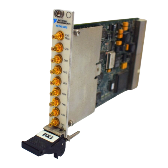
Using Your NI 4472 Connecting Signals The front panels of the NI 4472 for PCI and the NI 4472 for PXI/CompactPCI are shown in Figure 2-1. The NI 4472 has eight male SMB connectors on its front panel for connecting analog signals, and one male SMB connector for connecting a digital trigger. - Page 20 Chapter 2 Using Your NI 4472 NI 4472 FOR PXI TRIG TRIG NI 4472 for PXI/CompactPCI NI 4472 for PCI Figure 2-1. NI 4472 Front Panels © National Instruments Corporation NI 4472 User Manual...
-
Page 21: Signal Sources
Connecting a signal that varies more than ±2.5 V from the ground reference of the NI 4472 to the ground (shield) of any analog input channel can result in inaccurate measurements or damage to your device. National Instruments is not responsible for damage caused by such connections. -
Page 22: Floating Signal Sources
To ensure a good ground connection, securely fasten the front panel of the NI 4472 to the chassis with the screw that held the slot cover (NI 4472 for PCI) or two screws attached for that purpose (NI 4472 for PXI/CompactPCI). -
Page 23: Generating Onboard Current Excitation With Icp Circuitry
Input Coupling You can configure each analog input channel of the NI 4472 to be AC- or DC-coupled. If you select DC coupling, any DC offset present in the source signal is passed to the ADC. The DC-coupled configuration is usually best if the signal source has only small amounts of offset voltage (less than ±100 mV) or if the DC content of the acquired signal... -
Page 24: Input Polarity And Input Range
Using Test Panels to Acquire a Signal To quickly test your signal connections and the operation of your system, you can use the Test Panels to view a signal input to your NI 4472. To do so, follow these instructions: Connect a known signal to an analog input channel on the NI 4472. -
Page 25: Field Wiring Considerations
Field Wiring Considerations Environmental noise can affect the accuracy of measurements made with your NI 4472 if you do not take proper care when running signal wires between signal sources and the device. For more information, refer to National Instruments Application Note 025, Field Wiring and Noise Considerations for Analog Signals. -
Page 26: Selecting Your Sample Clock Frequency
♦ NI 4472 for PCI In a PCI system, any NI 4472 can be the master. The master broadcasts the ADC oversample clock to the other NI 4472 devices and synchronizes the start of the acquisition using reserved lines in the RTSI cable. -
Page 27: Device Configuration Issues
NI 4472 devices in other slots are slaves. The master broadcasts the ADC oversample clock to the other NI 4472 devices on the PXI Star trigger lines, and uses the RTSI 5/TRIG 5 line to synchronize the start of the acquisition. -
Page 28: Device Overview And Theory Of Operation
Device Overview and Theory of Operation This chapter presents an overview of the hardware functions of your NI 4472, and other useful information for understanding how the device works. Functional Overview Figure 3-1 shows a block diagram of the digital functions, and the analog function block diagram is shown in Figure 3-2. -
Page 29: I/O Connectors
NI 4472 can damage the device, the computer, and the associated accessories. National Instruments is not liable for any damage resulting from such signal connections. The front panel of the NI 4472 has nine SMB male connectors for attaching signal inputs. -
Page 30: Analog Input Signal Connections
±42.4 V, whether power is on or off. The shield side of the analog input channels has no overvoltage protection. Do not apply a signal that varies by more than ±2.5 V from the ground of the NI 4472. Analog Input Signal Connections Figure 3-3 shows a diagram of one of the eight identical NI 4472 analog input stages. -
Page 31: Calibration
The unbalanced differential analog inputs have software-selectable AC/DC coupling. Calibration The NI 4472 analog inputs have calibration adjustments. Onboard calibration circuits remove the offset and gain errors for each channel. For complete calibration instructions, refer to Chapter 4, Calibration. Antialias Filtering A sampling system (such as an ADC) can represent signals of only limited bandwidth. - Page 32 The NI 4472 includes a two pole anti-alias lowpass filter for each input channel. This filter has a cutoff frequency of about 400 kHz. Because its...
- Page 33 Frequency/Sample Rate (f Figure 3-4. Input Frequency Response Amplitude (dB) 0.00 –1.00 –2.00 –3.00 –4.00 –5.00 –6.00 0.43 0.44 0.45 0.46 0.47 0.48 0.49 0.50 Frequency/Sample Rate (f Figure 3-5. Input Frequency Response Near the Cutoff NI 4472 User Manual ni.com...
- Page 34 The alias rejection near 64 or 128 times the sample rate versus sample rate for the NI 4472 is illustrated in Figure 3-6. For frequencies not near multiples of the oversample rate, the rejection is better than 110 dB.
- Page 35 , 3.0 kHz sine waves. The signal-to-THD-plus-noise (THD+N) ratio is 35 dB for the clipped waveform and 92 dB for the properly ranged waveform. Aliases of all the harmonics due to clipping appear in Figure 3-7a. NI 4472 User Manual ni.com...
-
Page 36: The Adc
The ADC The NI 4472 ADC uses a method of A/D conversion known as delta-sigma modulation. If the data rate is 51.2 kS/s, each ADC actually samples its input signal at 6.5536 MS/s (128 times the data rate) and produces 1-bit samples that are applied to the digital filter. -
Page 37: Noise
Several factors can degrade the noise performance of the inputs. One of these factors is noise picked up from nearby electronic devices. The NI 4472 works best when it is kept as far away as possible from other plug-in devices, power supplies, disk drives, and computer monitors. -
Page 38: Trigger
Trigger In addition to supporting internal software triggering and external digital triggering to initiate a data acquisition sequence, the NI 4472 also supports analog-level triggering. You can configure the trigger circuit to monitor any one of the analog input channels to generate the level trigger. Choosing an input channel as the level trigger channel does not influence the input channel capabilities. - Page 39 Figure 3-9. Above-High-Level Triggering Mode In inside-region triggering mode, shown in Figure 3-10, the trigger is generated when the signal value is between lowValue and highValue. highValue lowValue Trigger Figure 3-10. Inside-Region Triggering Mode NI 4472 User Manual 3-12 ni.com...
- Page 40 Trigger Figure 3-12. Low-Hysteresis Triggering Mode You can use the EXT TRIG input SMB connector on the NI 4472 for dedicated external digital triggering. Alternately, you can trigger the NI 4472 from any other National Instruments device that has the RTSI-bus feature. You can...
-
Page 41: Device And Clocks
NI 4472 to use the internal timebase and place the NI 4472 in slot 2, you can program the device to drive its internal timebase over the PXI backplane to another NI 4472 that you program to receive this timebase signal. -
Page 42: Calibration
Loading Calibration Constants Your NI 4472 device is factory calibrated at approximately 25 °C to the levels indicated in Appendix A, Specifications. Before shipment, the associated calibration constants—the values that were written to the calibration circuitry to achieve calibration in the factory—are stored in the... -
Page 43: Self-Calibration
DC reference. The reference should be several times more accurate than the device itself. For example, to calibrate the NI 4472, the external reference should have a DC accuracy better than ±115 ppm (±0.001 dB). -
Page 44: Traceable Recalibration
Chapter 4 Calibration Note When you calibrate your NI 4472, make sure that ICP power is turned off to avoid affecting the reference voltage reading. Traceable Recalibration Traceable recalibration is divided into three different areas—factory, on-site, and third party. Devices typically require this type of recalibration every year. -
Page 45: Appendix A Specifications
Specifications This appendix lists the specifications of the NI 4472. These specifications are typical at 25 °C unless otherwise noted. The system must be allowed to warm up for 15 minutes to achieve the rated accuracy. Note Be sure to keep the filler panels on all unused slots in your chassis or computer to maintain forced air cooling. - Page 46 AC −3 dB cutoff frequency .....3.4 Hz Overvoltage protection Positive input ........±42.4 V Negative input (shield) ....Not protected Inputs protected .......CH<0..7> Common mode rejection ratio (CMRR) < 1 kHz ........> 60 dB, min Noise ............Refer to Figures A-1 through A-3 NI 4472 User Manual ni.com...
- Page 47 16,384 points, 51.2 kS/s, 10 averages 1.0 m 100.0 µ 10.0 µ 1.0 µ 100.0 n 10.0 n 10.0 100.0 1.0 k 10.0 k 25.6 k Frequency (Hz) Figure A-2. Input Noise Spectral Density at 128-Times Oversampling © National Instruments Corporation NI 4472 User Manual...
- Page 48 Stop band ..........0.5465 f Alias rejection.........110 dB Delay through ADC anti-aliasing filter ......38.8 sample periods Spurious free dynamic range ....130 dB, 1.0 kS/s ≤ f ≤ 51.2 kS/s 118 dB, ≤ 102.4 kS/s 51.2 kS/s < f NI 4472 User Manual ni.com...
- Page 49 ¯ 60.0 ¯ 80.0 ¯ 100.0 ¯ 120.0 ¯ 140.0 ¯ 160.0 5000 10000 15000 20000 25000 30000 35000 40000 45000 51194 Frequency (Hz) Figure A-5. Spurious-Free Dynamic Range at 102.4 kS/s © National Instruments Corporation NI 4472 User Manual...
- Page 50 Long-term stability .........±20 ppm/ 1,000 h Signal Conditioning Constant current source (software-enabled) Current..........4 mA, ±5% Compliance........24 V Output impedance......> 250 kΩ at 1 kHz Current noise ........< 500 pA/ Measured with full-scale (±10 V) input. NI 4472 User Manual ni.com...
- Page 51 Bus Interface Type ............Master, slave Power Requirements +3.3 VDC NI 4472 for PCI ......0 mA, max NI 4472 for PXI/CompactPCI ..400 mA, max +5 VDC NI 4472 for PCI ......2,600 mA, max NI 4472 for PXI/CompactPCI ..2,200 mA, max +12 VDC ..........
- Page 52 Appendix A Specifications Physical Dimensions (not including connectors) NI 4472 for PXI/CompactPCI ..16.0 by 9.9 cm (6.3 by 3.9 in.) (1 3U CompactPCI slot) NI 4472 for PCI .......17.5 by 10.7 cm (6.9 by 4.2 in.) Analog I/O connectors......SMB male Digital trigger connector......SMB male...
- Page 53 Acrobat icon to download or read the DoC. Category I refers to equipment for which measures are taken to limit transient overvoltages to a level lower than that of local-level mains supplies, such as telecommunications and protected electronic circuits. © National Instruments Corporation NI 4472 User Manual...
- Page 54 Technical Support Resources Web Support National Instruments Web support is your first stop for help in solving installation, configuration, and application problems and questions. Online problem-solving and diagnostic resources include frequently asked questions, knowledge bases, product-specific troubleshooting wizards, manuals, drivers, software updates, and more. Web support is available through the Technical Support section of ni.com...
- Page 55 Appendix B Technical Support Resources Worldwide Support National Instruments has offices located around the world to help address your support needs. You can access our branch office Web sites from the Worldwide Offices section of . Branch office Web sites provide ni.com...
- Page 56 AC coupled allowing the transmission of AC signals while blocking DC signals analog-to-digital converter—an electronic device, often an integrated circuit, that converts an analog voltage to a digital number © National Instruments Corporation NI 4472 User Manual...
- Page 57 Typically, a bus is the expansion vehicle to which I/O or other devices are connected. Examples of PC buses are the ISA and PCI bus. NI 4472 User Manual ni.com...
- Page 58 DAQ device to supply current for analog or digital output signals © National Instruments Corporation NI 4472 User Manual...
- Page 59 DAQ devices. SCXI modules are distinct from devices, with the exception of the SCXI-1200, which is a hybrid. differential input an analog input consisting of two terminals, both of which are isolated from computer ground, whose difference is measured NI 4472 User Manual ni.com...
- Page 60 A/D conversion © National Instruments Corporation NI 4472 User Manual...
- Page 61 Also called nonreferenced signal sources. Some common example of floating signal sources are batteries, transformers, or thermocouples. sampling frequency or rate gain the factor by which a signal is amplified, sometimes expressed in decibels grounded measurement See SE. system NI 4472 User Manual ni.com...
- Page 62 CPU should suspend its current task to service a designated activity interrupt request © National Instruments Corporation NI 4472 User Manual...
- Page 63 Instruments that implements the PCI bus interface. The MITE supports bus-mastering for high-speed data transfers over the PCI bus. million samples most significant bit normally closed, or not connected NI-DAQ National Instruments driver software for DAQ hardware NI 4472 User Manual ni.com...
- Page 64 Intel to replace ISA and EISA. It is achieving widespread acceptance as a standard for PCs and work-stations; it offers a theoretical maximum transfer rate of 132 Mbytes/s. programmable function input © National Instruments Corporation NI 4472 User Manual...
- Page 65 10% and 90% points of the step response of a system root mean square—the square root of the average value of the square of the instantaneous signal amplitude; a measure of signal amplitude NI 4472 User Manual G-10 ni.com...
- Page 66 Glossary See SE. RTSI bus real-time system integration bus—the National Instruments timing bus that connects DAQ devices directly, by means of connectors on top of the devices, for precise synchronization of functions seconds samples samples per second—used to express the rate at which a DAQ device...
- Page 67 0. For example, with 8-bit sound samples, two’s complement values would range from –128 to 127, with 0 meaning silence. See offset-binary format. NI 4472 User Manual G-12 ni.com...
- Page 68 Glossary unbalanced an analog input channel consisting of two terminals, with different input differential input impedances, whose difference is measured. In the case of the NI 4472, one terminal is referenced to ground through a resistor. See differential input. undersampling sampling at a rate lower than the Nyquist frequency—can cause aliasing...
- Page 69 A-2 CompactPCI antialias filtering, 3-4 to 3-9 clocks (timebases), 3-14 alias rejection at oversample rate installing NI 4472 for PXI/CompactPCI (figure), 3-8 (note), 2-2 comparison of clipped signal to proper using with PXI, 1-5 to 1-6 signal (figure), 3-9...
- Page 70 A-9 environment specifications, A-8 excitation of current, generating, 2-8 EXT TRIG connector, 2-9, 3-2 J2 connector pins used by NI 4472 (table), 1-6 external calibration, 4-2 to 4-3 LabVIEW software, 1-3 field wiring considerations, 2-10 filtering. See antialias filtering.
- Page 71 (figure), 3-3 onboard current excitation, generating with antialias filtering, 3-4 to 3-9 ICP circuitry, 2-8 calibration, 3-4 operation of NI 4472. See theory of operation. noise, 3-10 overranged waveform, 3-8 to 3-9 current excitation, generating with ICP circuitry, 2-8 ©...
- Page 72 (figure), 3-12 signal conditioning, A-6 device and clocks, 3-14 triggers digital trigger, 2-9 analog trigger, A-7 high-hysteresis triggering mode digital trigger, A-7 (figure), 3-13 synchronizing multiple devices, 2-11 to 2-12 system integration, by National Instruments, B-1 NI 4472 User Manual ni.com...
- Page 73 Index inside-region triggering mode (figure), 3-12 unpacking NI 4472, 1-3 low-hysteresis triggering mode (figure), 3-13 specifications analog trigger, A-7 Web support from National Instruments, B-1 digital trigger, A-7 Worldwide technical support, B-2 © National Instruments Corporation NI 4472 User Manual...
Need help?
Do you have a question about the NI 4472 and is the answer not in the manual?
Questions and answers