Table of Contents
Advertisement
Quick Links
Robot controller TSL3100
Robot controller TSL3100E
Robot controller TS3100
INSTRUCTION MANUAL
1.
Make sure that this instruction manual is delivered to the final
user of Toshiba Machine's industrial robot.
2.
Before operating the industrial robot, read through and
completely understand this manual.
3.
After reading through this manual, keep it nearby for future
reference.
TVL Series
MAINTENANCE MANUAL
Notice
April 2014
TOSHIBA MACHINE CO., LTD.
STE85440-4
Advertisement
Table of Contents

Related Manuals for Toshiba TVL Series


Summary of Contents for Toshiba TVL Series
- Page 1 MAINTENANCE MANUAL Notice Make sure that this instruction manual is delivered to the final user of Toshiba Machine's industrial robot. Before operating the industrial robot, read through and completely understand this manual. After reading through this manual, keep it nearby for future reference.
- Page 2 MAINTENANCE MANUAL This manual is applicable to the following robots. TVL Series: TVL500, TVL700 Copyright 2014 by Toshiba Machine Co., Ltd. All rights reserved. No part of this document may be reproduced in any form without obtaining prior written permission from Toshiba Machine Co., Ltd.
- Page 3 MAINTENANCE MANUAL WARRANTY This machine is delivered to each customer only after it is inspected very carefully to make sure that it satisfies the Toshiba Machine’s standard. Should it cause an inconvenience, we will guarantee as described below. Warranty period Toshiba Machine agrees to repair or replace as necessary all defective material or workmanship up to the period shown below, whichever comes first.
- Page 4 Please note that the warnings, cautions and other descriptions stipulated in this manual are only those which can be assumed by Toshiba Machine as of now. (*1) The consumable parts signify the replacement parts for maintenance as listed in Section 7 of this manual.
- Page 5 MAINTENANCE MANUAL INTRODUCTION This manual describes the TVL500/TVL700 industrial robot and TSL3100 controller, TSL3100E and TS3100. The maintenance and inspection are essential to maintain the robot performance for long years to prevent a trouble and improve the safe work. Before starting an actual operation, it is strongly recommended to read through this manual and draw up a maintenance schedule.
- Page 6 Disassembly caused. prohibited • Always use the Toshiba Machine's designated spare parts when replacing the parts. • Maintenance and inspection should be performed regularly. Mandatory Otherwise, the system may malfunction or accidents will be caused.
-
Page 7: Table Of Contents
MAINTENANCE MANUAL Table of Contents Page Maintenance ......................10 Maintenance Schedule .................. 10 Items for Maintenance and Inspection ............11 1.2.1 Inspection at Power OFF (at Non-Operation) ........11 1.2.2 Inspection at Power ON (at Operation) ..........12 1.2.3 Overhaul .................... 12 Maintenance Tools .................. - Page 8 MAINTENANCE MANUAL 3.3.3 Battery Replacement ................. 33 3.3.4 Replacement of Switching Power Supply Unit ........35 3.3.5 Replacement of Fuse (X8YX Printed Board Installed)....... 40 3.3.6 Replacement of Output ICs (X8YX Printed Board Installed) ..... 41 Maintenance of Controller (In case of TSL3100E) ..........45 Cautions on Maintenance and Inspection ............
- Page 9 MAINTENANCE MANUAL 6.5.1 Preparation before Restoring Operation ..........85 6.5.2 Setting New Home Position Data ............86 6.5.3 Confirming Home Position ..............87 6.5.4 Saving Data ..................88 Restoring Home Position Data by Multi-Turn Data Clear ....... 89 Axis Operation in Manual Mode ..............89 Replacement Parts for Maintenance...............
-
Page 10: Maintenance
MAINTENANCE MANUAL 1. Maintenance Maintenance Schedule Maintenance comes in the two (2) types: daily inspection, and regular inspection and maintenance. For the regular inspection and maintenance, inspection items are added every 1,200 running hours. 3-month 1200 check 3-month 6-month 2400 check check 3-month... -
Page 11: Items For Maintenance And Inspection
MAINTENANCE MANUAL Items for Maintenance and Inspection This section describes the items for maintenance and inspection. For the executing procedures, see the relevant paragraph listed in the table below. 1.2.1 Inspection at Power OFF (at Non-Operation) D: Daily inspection Q: Quarterly inspection S: Semi-annual inspection A: Annual inspection Description... -
Page 12: Inspection At Power On (At Operation)
Replace the switching power In the controller supply unit with a new one. Note: The items marked “●” may include some technical work. It is difficult for the customer to implement such work, so please ask Toshiba Machine Service Department. STE 85440... -
Page 13: Maintenance Tools
is marked in the above tables need special technical work. Do not attempt to carry out the work, and ask Toshiba Machine Service Department to deal with the inspection items. We recommend that the user contact Toshiba Machine Service Department and conclude an after-sale service contract with us. -
Page 14: Modification
1.4.3 Modification The robot and controller MUST NOT be modified or disassembled without a prior consent from Toshiba Machine. CAUTION • The user must NEVER replace or modify parts other than those described in the instruction manual. -
Page 15: Maintenance Of The Main Robot
MAINTENANCE MANUAL 2. Maintenance of the Main Robot Cautions on Maintenance and Inspection When performing inspection or maintenance of the robot, strictly observe the following precautions to protect yourself and coworkers. DANGER • Be sure to turn off the main power of the controller before approaching the robot for maintenance and inspection. - Page 16 MAINTENANCE MANUAL For the screws arranged on a circle, tighten them in the diagonal order, as shown below. DO NOT tighten one (1) screw at a time. Tighten each screw in multiple steps, using a hexagonal wrench key, and secure with appropriate clamping torque by means of a torque wrench.
-
Page 17: Tvl500/Tvl700 Structure And Components
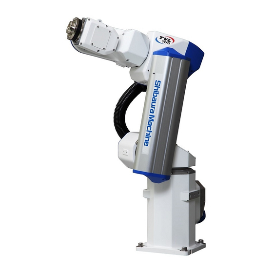
MAINTENANCE MANUAL TVL500/TVL700 Structure and Components * In this instruction manual, the diagrams of the TVL500 robot are used for the explanation. Arm 2 (1) Arm 1 Arm 3 Base Arm 2 (2) Base swivel Cable duct Fig. 2.1 Robot Structure and Components STE 85440... -
Page 18: Details Of Inspection
MAINTENANCE MANUAL Details of Inspection 2.3.1 Check of Each Bolt (or Screw) for Clamping Tool Set Bolts Make sure, using the hexagonal wrench key, that the hexagon socket head cap screws of the tool set flange, which are securing the arm 3 are tightened completely. -
Page 19: Checking The Cable Clamp For Looseness
MAINTENANCE MANUAL Robot Installation Bolts Make sure, using the hexagonal wrench key, that the installation bolts of the main robot base are tightened completely. If loosened, tighten them completely. Main robot installation bolt M10 x 4 pcs.; Recommended clamping torque 75 N·m Fig. -
Page 20: Dismounting And Mounting Each Cover
MAINTENANCE MANUAL Dismounting and Mounting Each Cover This paragraph describes the dismounting and mounting of the covers, which are common to the maintenance and replacement of each unit. DANGER • When opening the cover, take careful precautions not to allow entry of moisture or contaminant into the robot. -
Page 21: Base Covers
MAINTENANCE MANUAL 2.4.1 Base Covers The connector plate on the base rear is fixed to the connector panel by eight hexagon socket head bolts. When removing the connector plate, there is a restriction to the length of the cable of the base to be pulled out. -
Page 22: Arm-2 (1) Cover
MAINTENANCE MANUAL Base swivel cover Hexagon socket head cap screws M3 x 8 Fig. 2.6 Base swivel cover 2.4.3 Arm-2 (1) Cover The cover of the arm-2 (1) is directly fixed to the arm-2 (1) by five hexagon socket head bolts (M3 x 8) and five hexagon socket head bolts (M3 x 6). When mounting the cover, be careful that cables are not caught between the cover and the arm. -
Page 23: Arm-2 (2) Covers
MAINTENANCE MANUAL 2.4.4 Arm-2 (2) Covers The arm-2 (2) is provided with two covers on the right and left. The cover of the arm-2 (2) of the left drawing is fixed to the arm-2 (2) by six hexagon socket head bolts (M3 x 8) and one hexagon socket head bolt (M3 x 12). The cover of the arm-2 (2) of the right drawing is directly fixed to the arm-2 (2) by three hexagon socket head bolts (M3 x 8). -
Page 24: Replacing Position Detector (Or Encoder) Batteries
As a yardstick, the shutdown period is two (2) months. Note: Dedicated batteries must be used. For battery replacement, see Para. 7.1 and contact Toshiba Machine. CAUTION • When the battery voltage has dropped, a battery alarm will generate. If the batteries are replaced just after generation of the battery alarm, the battery voltage returns to normal with the battery alarm reset automatically. -
Page 25: Battery Unit Location
MAINTENANCE MANUAL 2.5.1 Battery Unit Location The position detector (or encoder) battery unit is installed in the base swivel. Base swivel cover Battery unit Base swivel Fig. 2.10 Battery unit location 2.5.2 Replacing Batteries DANGER • Only after assuring the safe work, replace the batteries with new ones while the power is turned on and an emergency stop is effected on the robot. -
Page 26: Battery Error Code
MAINTENANCE MANUAL Battery holder Battery Base swivel cover Battery unit Cross-recessed pan head machine screw M4 x 10 (The screws should be only loosened.) Fig. 2.11 Replacing batteries Mount the base swivel cover to the original place. This completes the replacement of batteries. - Page 27 In the first place, replace the battery. If the error recurs even after battery replacement, the encoder may be faulty. In this case, the motor needs to be replaced. Please ask Toshiba Machine Service Department to replace it. Table 2.3 8-61* battery error codes...
-
Page 28: Maintenance Of Controller (In Case Of Tsl3100)
MAINTENANCE MANUAL 3. Maintenance of Controller (In case of TSL3100) Cautions on Maintenance and Inspection When performing maintenance and inspection of the controller, follow the items given below so that the work can be carried out safely. DANGER • If the power is kept turned on, the servo power printed board, servo printed board and switching power supply are electrostatically charged. -
Page 29: Layout Of Controller Parts
MAINTENANCE MANUAL Layout of Controller Parts TSL3100 Parts Layout X8YW unit servo X8YC (Main control power printed board printed board) X8YS unit servo power PS1(P5V,P24V) printed board X8YX (I/O printed board) Controller weight: 9kg Fig. 3.1 Layout of controller parts (TSL3100) Table 3.1 Controller parts (TSL3100) Part name Descriptions... -
Page 30: Maintenance Procedures
MAINTENANCE MANUAL Maintenance Procedures 3.3.1 Check of Controller Air Vent Holes If the air vent holes are blocked, the controller may overheat and malfunction. To avoid this, perform check on the air vent holes to make sure that air is flowing freely through them. -
Page 31: Check Of Safety Devices For Function
MAINTENANCE MANUAL If there is any obstacle, move it away from the air vent hole so that air flow is not blocked. Make sure that no contaminant is left on the air vent holes. If any contaminant is left on the vent hole, remove it. 3.3.2 Check of Safety Devices for Function Make sure that the EMERGENCY stop pushbutton switches equipped on the control panel and teach pendant work properly. - Page 32 MAINTENANCE MANUAL [1] [2] Note: The above figure is of the TP1000. For the TP3000, see the "TP3000 Instruction Manual: Operation." Fig. 3.4 EMERGENCY STOP switch provided on teach pendant Make sure that the safety devices controlled by the external operation input signals work properly.
-
Page 33: Battery Replacement
MAINTENANCE MANUAL 3.3.3 Battery Replacement The memory equipped on the X8YC printed board of the robot controller is backed up by a lithium battery to save the data. Replace the battery every five (5) years. The lithium battery will turn its life when used for a predetermined time. If it is used, neglecting the life, the battery voltage will drop to below the voltage required for keeping the memory data, resulting in the data being lost and faults caused by leakage of the battery liquid. - Page 34 (5) years. Only the battery shown in the table above should be used. As this is an exclusive battery, contact Toshiba Machine at order entry. [Battery replacement procedures] If the battery is to be kept removed for more than one (1) minute, copy all programs and various parameters stored in the internal memory to the personal computer.
-
Page 35: Replacement Of Switching Power Supply Unit
MAINTENANCE MANUAL CAUTION • Waste battery should be disposed of according to the user's in-house regulations. NEVER drop the battery into fire. NEVER short-circuit, charge, disassemble or heat it. Otherwise, liquid leakage or rupture may be caused. 3.3.4 Replacement of Switching Power Supply Unit The life of the switching power supply unit (5 VDC/24 VDC) used in the robot controller differs with the operating conditions. - Page 36 MAINTENANCE MANUAL Nine flat countersunk head screws (M3 x 6) To remove the intermediate plate unit, remove the key. ACIN connector Fig. 3.6 Removal of cover. (TSL3100) 5) Remove the DC cables (blue and red), SVIF cable (blue) and encoder cable (blue) connected to the X8YC (main printed board), and the hand I/O cable (blue) and brake cable (blue) connected to the X8YX (I/O printed board).
- Page 37 MAINTENANCE MANUAL Encoder cable (blue) X8YC (main printed board) Brake cable (blue) DC cables (blue and red) X8YX (I/O printed board) SVIF cable (blue) Hand I/O cable (blue) Fig. 3.7 Controller interior (side view) (TSL3100) Encoder cable (blue) X8YC (main printed board) Fig.
- Page 38 MAINTENANCE MANUAL 7) Remove one flat countersunk head screws (M3 x 6) from the intermediate plate unit. Remove the intermediate plate unit toward the back of the controller. To remove the intermediate plate unit, be sure to remove the key. Remove the intermediate plate unit.
- Page 39 MAINTENANCE MANUAL DC cable (blue) AC cable (black, PS1) DC side AC side Four sems screws (M3 x 8) PS1 (P5V, P24V) LFB100F-0524 8) Remove four sems screws (M3 x 8) fixing the switching power supply (PS1) from the switching power supply and remove the switching power supply from the intermediate plate unit.
-
Page 40: Replacement Of Fuse (X8Yx Printed Board Installed)
MAINTENANCE MANUAL 3.3.5 Replacement of Fuse (X8YX Printed Board Installed) If the current exceeding the specified current has run through the I/O unit, the fuse of in the front of the controller is blown out. If the alarm saying “I/O Fuse broken (8– 273)”... -
Page 41: Replacement Of Output Ics (X8Yx Printed Board Installed)
MAINTENANCE MANUAL Table 3.3 Fuse replacement (TSL3100) Type of fuse Manufacturer 51NM030H PICO Inc. [Replacement procedures] 1) Remove the power source plug of the controller body from the power source. 2) Remove the fuse holder shown in the above figure. (It is unlocked by pushing and turning 90... - Page 42 There are two types of output IC for the transistor output IC. For the output type, see the table below. Table 3.4 Transistor output IC (TSL3100) Output type Transistor output IC model Manufacturer Type-N TD62084APG Toshiba Corp. Mitsubishi Electric Type-P M54562WP STE 85440...
- Page 43 MAINTENANCE MANUAL [Replacement procedures] 1) Turn off the power supply circuit breaker. 2) Remove the ACIN connector from the controller. 3) Remove nine flat countersunk head screws (M3 x 6) fixing the cover and remove the cover from the main unit. Nine flat countersunk head screws (M3 x 6) Fig.
- Page 44 MAINTENANCE MANUAL X8YX (I/O printed board) Four sems screws (M3 x 8) Brake cable (blue) Hand I/O cable (blue) Fig. 3.14 Removal of X8YX printed board (TSL3100) 6) Remove the transistor output IC of Figure 3.12 from the socket. 7) Mount a new transistor output IC on the socket. Note) Pay attention to the transistor output IC's model number and mounting direction.
-
Page 45: Maintenance Of Controller (In Case Of Tsl3100E)
MAINTENANCE MANUAL 4. Maintenance of Controller (In case of TSL3100E) Cautions on Maintenance and Inspection When performing maintenance and inspection of the controller, follow the items given below so that the work can be carried out safely. DANGER • If the power is kept turned on, the servo power printed board, servo printed board and switching power supply are electrostatically charged. -
Page 46: Layout Of Controller Parts
MAINTENANCE MANUAL Layout of Controller Parts TSL3100E Parts Layout Safety relay modules (SRM1, SRM2) X8YW (unit servo power printed board) X8YV (Main control printed boar) X8YJ (I/O printed board) PS1 (P5V,P24V) X8YS (unit servo power printed board) X8YZ (Safety input board) Controller weight: 11.4kg Fig. -
Page 47: Maintenance Procedures
MAINTENANCE MANUAL Maintenance Procedures 4.3.1 Check of Controller Air Vent Holes If the air vent holes are blocked, the controller may overheat and malfunction. To avoid this, perform check on the air vent holes to make sure that air is flowing freely through them. -
Page 48: Check Of Safety Devices For Function
MAINTENANCE MANUAL If there is any obstacle, move it away from the air vent hole so that air flow is not blocked. Make sure that no contaminant is left on the air vent holes. If any contaminant is left on the vent hole, remove it. 4.3.2 Check of Safety Devices for Function Make sure that the EMERGENCY stop pushbutton switches equipped on the control panel and teach pendant work properly. - Page 49 MAINTENANCE MANUAL [1] [2] Note: The above figure is of the TP1000. For the TP3000, see the "TP3000 Instruction Manual: Operation." Fig. 4.4 EMERGENCY STOP switch provided on teach pendant Make sure that the safety devices controlled by the external operation input signals work properly.
-
Page 50: Battery Replacement
MAINTENANCE MANUAL 4.3.3 Battery Replacement The memory equipped on the X8YV printed board of the robot controller is backed up by a lithium battery to save the data. Replace the battery every five (5) years. The lithium battery will turn its life when used for a predetermined time. If it is used, neglecting the life, the battery voltage will drop to below the voltage required for keeping the memory data, resulting in the data being lost and faults caused by leakage of the battery liquid. - Page 51 MAINTENANCE MANUAL Only the battery shown in the table above should be used. As this is an exclusive battery, contact Toshiba Machine at order entry. [Battery replacement procedures] If the battery is to be kept removed for more than one (1) minute, copy all programs and various parameters stored in the internal memory to the personal computer.
-
Page 52: Replacement Of Switching Power Supply Unit
MAINTENANCE MANUAL 4.3.4 Replacement of Switching Power Supply Unit The life of the switching power supply unit (5 VDC/24 VDC) used in the robot controller differs with the operating conditions. This unit uses an aluminum electrolytic capacitor, and if the load current is large, the running time is long and the ambient temperature is high, the life will reduce. - Page 53 MAINTENANCE MANUAL [Replacement procedures] 1) Turn off the power supply circuit breaker and remove the power plug from the power source. 2) Remove the ACIN connector from the controller. 3) Remove the key from the controller. 4) Remove ten flat countersunk head screws (M3 x 6) fixing the cover and remove the cover from the main unit.
- Page 54 MAINTENANCE MANUAL X8YJ (I/O printed board) X8YV (main printed board) X8YZ (Safety input board) Brake cable (blue) DC cables (blue and red) Hand I/O cable (blue) SVIF cable (blue) Fig. 4.7 Controller interior (side view) (TSL3100E) Encoder cable (blue) Fig. 4.8 Controller interior (lateral front view) (TSL3100E) STE 85440...
- Page 55 MAINTENANCE MANUAL 7) Remove three flat countersunk head screws (M3 x 6) from the intermediate plate unit. Remove the intermediate plate unit toward the back of the controller. To remove the intermediate plate unit, be sure to remove the key. three flat countersunk head screws (M3 x 6) Remove the intermediate plate unit.
- Page 56 MAINTENANCE MANUAL 8) Remove four sems screws (M3 x 8) fixing the switching power supply (PS1) from the switching power supply and remove the switching power supply from the intermediate plate unit. DC cable (blue) AC cable (black, PS1) DC side AC side Four sems screws PS1 (P5V, P24V) LFB100F-0524...
-
Page 57: Replacement Of Fuse (X8Yj Printed Board Installed)
MAINTENANCE MANUAL 4.3.5 Replacement of Fuse (X8YJ Printed Board Installed) If the current exceeding the specified current has run through the I/O unit, the fuse of in the front of the controller is blown out. If the alarm saying “I/O Fuse broken (8– 273)”... - Page 58 MAINTENANCE MANUAL Table 4.3 Fuse replacement (TSL3100) Type of fuse Manufacturer 51NM030H PICO Inc. [Replacement procedures] 1) Remove the power source plug of the controller body from the power source. 2) Remove the fuse holder shown in the above figure. (It is unlocked by pushing and turning 90...
-
Page 59: Maintenance Of Controller (In Case Of Ts3100)
MAINTENANCE MANUAL 5. Maintenance of Controller (In case of TS3100) Cautions on Maintenance and Inspection When performing maintenance and inspection of the controller, follow the items given below so that the work can be carried out safely. CAUTION • To remove the cover of the controller for maintenance and inspection, be sure to remove the controller power plug before you start your work. -
Page 60: Controller Component Layout
MAINTENANCE MANUAL Controller Component Layout TSL3100E Parts Layout X8GM X8G1 to X8G3 X8GN (X8GI) X8GC X8GL Lower side of capacitor Controller weight: 17kg Fig. 5.1 Controller component layout diagram (TS3100) Table 5.1 Controller components (TS3100) Name Description P5V/P24V output switching power supply unit X8GC Main control printed board X8GN (X8GI) -
Page 61: Maintenance Procedure
MAINTENANCE MANUAL Maintenance Procedure 5.3.1 Checking the Status of the Controller's Air Vent Holes If the air vent holes of the controller are blocked, the temperature inside the controller will rise abnormally, causing the controller to malfunction. Perform the following inspections to make sure that the air vent holes are completely open. -
Page 62: Checking The Safety Device Function
MAINTENANCE MANUAL 5.3.2 Checking the Safety Device Function Check that the emergency stop switch on the control panel and that on the teaching pendant as well as the function of each of the safety devices being connected to the external operation input signals are normal. Fig. - Page 63 MAINTENANCE MANUAL 3) Press down the emergency stop switch [2] on the control panel and check that the servo turns OFF. The LED of the SERVO ON switch [1] goes off and the LED of the SERVO OFF switch illuminates. Check that the emergency stop switch [2] is being held down at this time.
- Page 64 MAINTENANCE MANUAL [5] [6] * This figure shows the layout for the TP1000. For the TP3000, see the "TP3000 Instruction Manual: Operation." Fig. 5.4 Emergency stop switch on the teaching pendant (TS3100) c) Make sure that the safety devices being connected to the external operation input signals function properly.
-
Page 65: Battery Replacement
MAINTENANCE MANUAL 5.3.3 Battery Replacement The memory contained on the X8GC printed board of the robot controller is backed up by a lithium battery to save the data. As a guideline, replace the battery every five (5) years. The lithium battery will reach its end of life when used for a predetermined time. - Page 66 (5) years. Only the battery shown in the table above must be used as a replacement battery; because this is a special battery, contact Toshiba Machine to order this battery.
- Page 67 MAINTENANCE MANUAL Replacement Procedure 1) If you intend to remove the battery for one (1) minute or longer, back up all the programs and parameters stored in memory to your computer. Otherwise, all the data in memory will be lost. 2) Turn OFF the MAIN POWER switch.
-
Page 68: Replacement Of Switching Power Supply Unit
COSEL CO., LTD. Note: The switching power supply unit shown in the table above must be used as a replacement switching power supply unit; because this is a special product, please contact Toshiba Machine to order this item. STE 85440... -
Page 69: Replacement Of Fuse
MAINTENANCE MANUAL 5.3.5 Replacement of Fuse When the current exceeding the specification value flows through the I/O unit, the fuse in the front of the controller blows out. If the "I/O Fuse Broken" (8–273) alarm is displayed, the fuse has blown out, so replace the fuse with a new one. - Page 70 MAINTENANCE MANUAL Replacement Procedure 1) Turn OFF the power to the controller body. 2) Remove the fuse holder shown in the figure above. (The fuse holder can be unlocked by turning it 90 º counterclockwise while holding it down.) 3) Remove the blown fuse and set a new fuse in the fuse holder. 4) Mount the removed fuse holder.
-
Page 71: Replacement Of Output Ics (X8Gc And X8Gn (X8Gi) Printed Boards)71
MAINTENANCE MANUAL 5.3.6 Replacement of Output ICs (X8GC and X8GN (X8GI) Printed Boards) When the current exceeding the specification value flows into the output section, the ICs of the X8GC and X8GN (X8GI) printed boards will be damaged. If this happens, replace the ICs. Before replacing the ICs, carefully examine and identify faulty circuits, remedy the cause, and then replace the ICs. - Page 72 MAINTENANCE MANUAL [2] Output IC U3 User output signal: DOUT1 to DOUT8 Connector: OUTPUT [2] Output IC U4 [1] Output ICs User output signal: DOUT9~DOUT16 * Each signal Connector: OUTPUT names is the same as [2] Output IC U5 those in the User output signal: figure at right.
- Page 73 MAINTENANCE MANUAL Table 5.5 Output section ICs (TS3100) Printed board IC part number Manufacturer X8GN TD62082AP Toshiba Corporation X8GI M54562WP Mitsubishi Electric Corporation Replacement Procedure 1) Turn OFF the power to the controller body. 2) Remove the cover from the controller body.
-
Page 74: Robot Home Point And Position Detector Error
MAINTENANCE MANUAL 6. Robot Home Point and Position Detector Error Setting Robot Home Point Before delivery from our plant, home point setting is performed for the robot after its arm is secured with clamp for home point setting. At the time of home point setting, position data of the motor position detector (i.e., encoder) is backed up by batteries, and coordinates of the robot need not be set each time the power is turned on. -
Page 75: Position Detector Error
MAINTENANCE MANUAL Position Detector Error If a position detector error (encoder error) occurs, errors as shown below are shown on the error display of the teach pendant. To view the error display, press the [ERROR] key on the teach pendant. For the types of errors, see Para. 2.5.3. C U R R E N T A L A R M [ 1 / 1 ]... - Page 76 MAINTENANCE MANUAL When the mechanical connecting position with the motor has changed after motor or belt replacement: A position detector error may occur after replacement and adjustment of the servo motor or timing belt. When this happens, execute the following restoring operation.
- Page 77 See Para. 6.7 for the movement of each axis in manual mode. 2.1.1) When the error occurs again: The position detector has possibly malfunctioned. Contact Toshiba Machine. 2.1.2) When the error will not occur again: Move each axis at low speed in JOG mode and check the axis travel range.
-
Page 78: Restoring Operation From Position Detector Error
MAINTENANCE MANUAL Restoring Operation from Position Detector Error Make sure on the error display that a position detector error is generated. Identify the type of the position detector error and position data on the encoder status screen, then perform each restoring operation. 6.3.1 Encoder status screen Call the encoder status screen on the teach pendant display, and make sure of the position data and the type of position detector error there. -
Page 79: Encoder Error Reset Operation
MAINTENANCE MANUAL Set the master mode switch to the TEACHING mode, and press the [UTILITY] key on the teach pendant. Make sure that the display mode has changed to the UTILITY mode, and press the [NEXT] key once. Press [ENC] ([F5] key) that has appeared on the function menu. The following encoder status screen is displayed. -
Page 80: Restoring Home Position Data By Home Function
MAINTENANCE MANUAL M U L T I S I N G L E E r r - d f 0 0 0 0 1 2 3 4 0 2 0 0 0 0 0 0 1 2 3 4 0 2 0 0 0 0 0 0 1 2 3 4 4 2 0 0 0 0 0 0 1 2 3 4... -
Page 81: Setting Home1 And Home2
MAINTENANCE MANUAL (Page 1) U S E R H O M E 1 H O M E 2 ( J 1 ) [ d e g ] ( J 2 ) [ d e g ] ( J 3 ) [ d e g ] ( J 4 ) [ d e g ]... -
Page 82: How To Restore Data By Home1 Or Home2
MAINTENANCE MANUAL Data is set by pressing the [TEACH] (F4) key. U S E R H O M E 1 H O M E 2 ( J 1 ) [ d e g ] ( J 2 ) [ d e g ] ( J 3 ) [ d e g ] ( J 4 ) -
Page 83: Locations Of Robot Home Point Match-Marks
MAINTENANCE MANUAL 6.4.4 Locations of Robot Home Point Match-Marks * In this instruction manual, the drawings for the TVL500 robot are used in the explanations. Axis 5 home point Axis 6 home point match-mark match-mark Axis 1 home point See the match-mark detail view E. -
Page 84: How To Restore Data By Home3 Or Home4
MAINTENANCE MANUAL 6.4.5 How to Restore Data by HOME3 or HOME4 The plus (+) side mechanical stopper positions and minus (–) side mechanical stopper positions of the axes 1 to 3 and 5 are factory-set in HOME3 and HOME4, respectively. The axis 4 and axis 6 set to the home point match-mark. The robot home point can be restored, using the above. -
Page 85: Preparation Before Restoring Operation
MAINTENANCE MANUAL 6.5.1 Preparation before Restoring Operation Turn on the controller power, release the brake, and align the home point match-marks of each axis in manual mode. See Para. 6.4.4 for the positions of home point match-marks. See Para. 6.7 for the movement of each axis in manual mode. -
Page 86: Setting New Home Position Data
MAINTENANCE MANUAL 6.5.2 Setting New Home Position Data Set the master mode switch to the TEACHING mode and press the [UTILITY] key on the teach pendant. Make sure that the display mode has changed to the UTILITY mode, then press the [NEXT] key twice. -
Page 87: Confirming Home Position
MAINTENANCE MANUAL Z E R O P O S I T I O N E 1 : - 7 5 0 0 0 E 2 : 1 3 9 9 8 0 0 E 3 : 5 8 0 9 E 4 : 2 9 0 0 0 0 E 5 :... -
Page 88: Saving Data
MAINTENANCE MANUAL In reference to the following program, create a program that moves the robot to the reference position you have set in step 2 in Para. 6.5.1, and make sure that the robot moves to the reference position correctly. PROGRAM ZERO SPEED=20 MOVEA 6,0... -
Page 89: Restoring Home Position Data By Multi-Turn Data Clear
MAINTENANCE MANUAL Restoring Home Position Data by Multi-Turn Data Clear The motor multi-turn data may be cleared due to a drop in the battery voltage (in which case the error status code 4000 in Table 4.1 is displayed) or another event. Replace the batteries (see Para. - Page 90 MAINTENANCE MANUAL Press the Enable switch (see Para 3.3.2 (b).) on the teach pendant by one step. Then the menu items [LOCK] and [FREE] are displayed on the function menu, and data can be edited. M O T O R B R A K E C O N T R O L 4 / 4...
-
Page 91: Replacement Parts For Maintenance
With the exception of the encoder backup batteries, all parts listed below are custom-made to Toshiba Machine specifications. Contact Toshiba Machine at order entry. • Parts replacement work must be done by Toshiba Machine service engineer. Toshiba Machine’s warranty does not cover failures, accidents or any damages. STE 85440... -
Page 92: List Of Replacement Parts - Main Robot (Tvl500/Tvl700)
MAINTENANCE MANUAL List of Replacement Parts – Main Robot (TVL500/TVL700) Q’ty Part name Toshiba Dwg. No. Unit code Maker Remarks S 9 0 7 9 6 4 Y610A3UF0 Axis 1, 2 Toshiba AC servo motor S 9 0 7 9 6 5... -
Page 93: List Of Replacement Parts - Controller (For The Tsl3100E)
MAINTENANCE MANUAL List of Replacement Parts – Controller (for the TSL3100E) Q’ty Part name Toshiba Dwg. No. Unit code Maker Remarks PS1 (Switching power P5V, P24V power LEB100F-0524 Kosel Co., Ltd. supply) source Hitachi Maxell Lithium battery ER6C WK27 X8YV printed board Co., Ltd. -
Page 94: Servo Amplifier Corresponding Table
MAINTENANCE MANUAL From *1, *3 and *4, please select the compatible items with the machine model you use. *2 In the case of the TS3100CE or TS3100E Servo Amplifier Corresponding Table Servo amplifier module type X8G2A 15A X8G3A 10A X8G3B 5A (1st axis, 2nd axis) (3rd axis) (4th axis, 5th axis, 6th axis)
Need help?
Do you have a question about the TVL Series and is the answer not in the manual?
Questions and answers