
Related Manuals for EWM Cool XQ 40


Summary of Contents for EWM Cool XQ 40
- Page 1 Operating instructions Air-cooling units for water-cooled welding torches Cool XQ 40 Cool XQ 40 MV 099-005632-EW501 Observe additional system documents! 26.10.2022...
- Page 2 +49 2680 181-0. A list of authorised sales partners can be found at www.ewm-group.com/en/specialist-dealers. Liability relating to the operation of this equipment is restricted solely to the function of the equipment. No other form of liability, regardless of type, shall be accepted.
-
Page 3: Table Of Contents
Checklist for rectifying faults ....................31 Vent coolant circuit ....................... 32 Fixing the pump shaft (coolant circuit) ................. 33 8 Technical data ..........................34 Cool XQ 40 .......................... 34 9 Accessories ..........................35 Welding torch cooling system ....................35 9.1.1 Coolant - type blueCool .................. -
Page 4: For Your Safety
For your safety Notes on using these operating instructions For your safety Notes on using these operating instructions DANGER Working or operating procedures which must be closely observed to prevent imminent serious and even fatal injuries. • Safety notes include the "DANGER" keyword in the heading with a general warning symbol. •... -
Page 5: Explanation Of Icons
For your safety Explanation of icons Explanation of icons Symbol Description Symbol Description Indicates technical aspects which the Activate and release / Tap / Tip user must observe. Switch off machine Release Switch on machine Press and hold Incorrect / Invalid Switch Correct / Valid Turn... -
Page 6: Safety Instructions
For your safety Safety instructions Safety instructions WARNING Risk of accidents due to non-compliance with the safety instructions! Non-compliance with the safety instructions can be fatal! • Carefully read the safety instructions in this manual! • Observe the accident prevention regulations and any regional regulations! •... - Page 7 For your safety Safety instructions WARNING Risk of injury due to improper clothing! During arc welding, radiation, heat and voltage are sources of risk that cannot be avoided. The user has to be equipped with the complete personal protective equipment at all times.
- Page 8 For your safety Safety instructions CAUTION Smoke and gases! Smoke and gases can lead to breathing difficulties and poisoning. In addition, solvent vapour (chlorinated hydrocarbon) may be converted into poisonous phosgene due to the ultraviolet radiation of the arc! • Ensure that there is sufficient fresh air! •...
-
Page 9: Transport And Installation
For your safety Transport and installation CAUTION Obligations of the operator! The respective national directives and laws must be complied with when operating the machine! • Implementation of national legislation relating to framework directive 89/391/EEC on the int- roduction of measures to encourage improvements in the safety and health of workers at work and associated individual guidelines. - Page 10 For your safety Transport and installation CAUTION Risk of accidents due to supply lines! During transport, attached supply lines (mains leads, control cables, etc.) can cause risks, e.g. by causing connected machines to tip over and injure persons! • Disconnect all supply lines before transport! Risk of tipping! There is a risk of the machine tipping over and injuring persons or being damaged itself during movement and set up.
-
Page 11: Intended Use
The following system components can be combined: Power source Tetrix XQ 230 puls DC Tetrix XQ 230 puls AC/DC Machine control Comfort 3.0 Expert 3.0 Welding torch cooling unit Cool XQ 40 Cool XQ 40 MV Transport vehicle Trolly XQ 35-3 Trolly XQ 55-3 099-005632-EW501 26.10.2022... -
Page 12: Documents Which Also Apply
3.3.1 Warranty For more information refer to the "Warranty registration" brochure supplied and our information regarding warranty, maintenance and testing at www.ewm-group.com! 3.3.2 Declaration of Conformity This product corresponds in its design and construction to the EU directives listed in the decla- ration. -
Page 13: Part Of The Complete Documentation
Intended use Documents which also apply 3.3.4 Part of the complete documentation This document is part of the complete documentation and valid only in combination with all other parts of these instructions! Read and observe the operating instructions for all system components, especially the safety instructions! The illustration shows a general example of a welding system. -
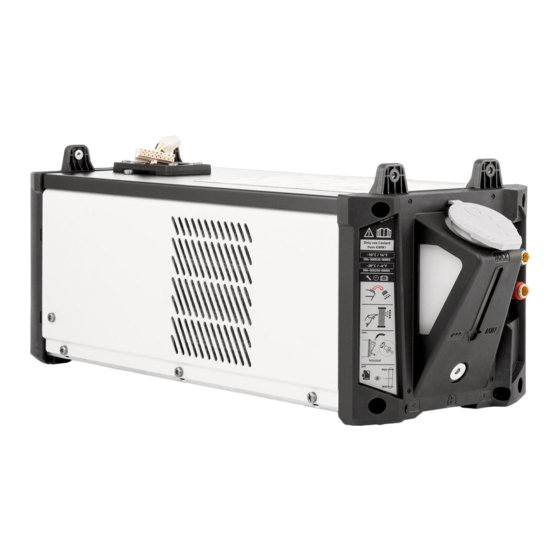
Page 14: Machine Description - Quick Overview
Machine description – quick overview Front view / rear view Machine description – quick overview Front view / rear view Figure 4-1 099-005632-EW501 26.10.2022... - Page 15 Machine description – quick overview Front view / rear view Item Symbol Description Module connector Screw connection for system components Coolant tank > see 5.2.3 chapter Machine feet Cooling air inlet Service opening for coolant pump > see 7.3 chapter Holder for the module connector Screw connection for module fastening of system components Cooling air outlet...
-
Page 16: Design And Function
Design and function Connect the cooling unit to the power source Design and function WARNING Risk of injury from electrical voltage! Contact with live parts, e.g. power connections, can be fatal! • Observe the safety information on the first pages of the operating instructions! •... - Page 17 Design and function Connect the cooling unit to the power source Figure 5-1 1 Switch off the power source and disconnect the mains plug. 2 Place the power source to the side. 3 Loosen the screws on the lower cover. Move the cover to the park position towards the front. Screw the cover back on.
-
Page 18: Transport And Installation
Design and function Transport and installation 4 Undo all four Torx screws from the module connectors of the cooling unit. 5 Route the supply lines through the cable duct of the cooling unit. 6 Place the power source with the front feet ahead of the front module connector of the cooling unit. Lift the power source at the rear and plug both connectors of the cooling unit’s supply lines into the corres- ponding sockets of the power source (the connectors must engage). -
Page 19: Welding Torch Cooling System
All information relates to the total hose package length of the complete welding system and presents exemplary configurations (of components of the EWM product portfolio with standard lengths). A straight kink-free installation is to be ensured, taking into account the max. delivery height. -
Page 20: Adding Coolant
Design and function Transport and installation 5.2.3.4 Adding coolant After switching on the machine, the coolant pump runs for a defined time (filling the hose package). If the machine does not detect sufficient coolant flow during this time, the coolant pump is switched off (protec- tion against damage caused by dry running). -
Page 21: Welding Torch Connection
Design and function Transport and installation 5.2.4 Welding torch connection The cooling circuit (cooling unit <> welding torch) must not be interrupted. Otherwise, the coo- lant pump can be destroyed by thermal overload (the coolant cannot circulate). When using air- cooled welding torches, one of the following measures must be taken depending on the ma- chine version: •... -
Page 22: Maintenance, Care And Disposal
Maintenance, care and disposal General Maintenance, care and disposal General WARNING Improper maintenance, testing and repairs! Maintenance, testing and repair of the machine may only be carried out by skilled and qualified personnel (authorised service personnel). A competent person is someone who, based on training, knowledge and experience, can recognize the hazards and pos- sible consequential damage that may occur when testing power sources and can take the necessary safety precautions. -
Page 23: Explanation Of Icons
Maintenance, care and disposal Explanation of icons Explanation of icons Personnel Welder / operator Qualified person (authorised service personnel) Tests Visual inspection Functional test Period, interval One-shift operation Multi-shift operation Every 8 hours Daily Weekly Monthly Every 6 months Annually 099-005632-EW501 26.10.2022... -
Page 24: Maintenance Schedule
Maintenance, care and disposal Maintenance schedule Maintenance schedule Maintenance step Only personnel designated as inspectors or repairers due to their trai- ning are allowed to carry out the relevant work step! Inapplicable checkpoints are omitted. • Check and clean the welding torch. Deposits in the welding torch may cause short circuits, impair the welding result and lead to welding torch damage! •... -
Page 25: Coolant Error
Maintenance, care and disposal Maintenance schedule 6.3.1 Coolant error Figure 6-1 • Switch off the machine and disconnect the mains plug. Position a suitable collecting container under the drain plug of the coolant tank. • Unscrew the drain plug of the coolant tank (remove the tank cap to ventilate). Figure 6-2 •... -
Page 26: Dirt Filter
Insert the cleaned filter screen into the filler neck and screw the drain plug with seal back into the tank. • Fill the tank with original EWM coolant up to the maximum level. After filling, refit the tank cap and vent the coolant circuit > see 7.2 chapter. -
Page 27: Power Source (Inverter)
Maintenance, care and disposal Maintenance schedule 6.3.3 Power source (inverter) WARNING Risk of injury due to insufficient training! Appropriate training is required for the following maintenance steps to prevent injuries. • Only authorised service personnel may carry out this maintenance step. •... - Page 28 Maintenance, care and disposal Maintenance schedule Figure 6-7 • Clean the machine fan with compressed air free of oil and water. Block the fan wheel of the machine fan mechanically (the machine fan may over-rotate due to the compressed air and be damaged as a result)! •...
-
Page 29: Heat Exchanger (Torch Cooling)
Maintenance, care and disposal Maintenance schedule Figure 6-9 • Reconnect all four power lines to the main switch (note inputs / outputs). • Reinstall the side panels and secure with the screws. • Check the machine according to applicable regulations. 6.3.4 Heat exchanger (torch cooling) WARNING... -
Page 30: Annual Test (Inspection And Testing During Operation)
Information on returning used equipment or collections can be obtained from the respective municipal administration office. Devices can also be returned to EWM sales partners across Europe. Further information on the topic of the disposal of electrical and electronic equipment can be found on our website at: https://www.ewm-group.com/de/nachhaltigkeit.html. -
Page 31: Rectifying Faults
Rectifying faults Checklist for rectifying faults Rectifying faults All products are subject to rigorous production checks and final checks. If, despite this, something fails to work at any time, please check the product using the following flowchart. If none of the fault rectification procedures described leads to the correct functioning of the product, please inform your authorised dea- ler. -
Page 32: Vent Coolant Circuit
Rectifying faults Vent coolant circuit Vent coolant circuit Figure 7-1 • Switch off the machine and fill the coolant tank to the maximum level. • Unlock the quick-connect coupling with a suitable tool (connection open). To vent the cooling system always use the blue coolant connection, which is located as deep as possible inside the system (close to the coolant tank)! Figure 7-2 •... -
Page 33: Fixing The Pump Shaft (Coolant Circuit)
Rectifying faults Fixing the pump shaft (coolant circuit) Fixing the pump shaft (coolant circuit) WARNING No improper repairs and modifications! To prevent injuries and damage to the machine, only competent personnel (authorised service personnel) are allowed to repair or modify the machine. Unauthorised manipulations will invalidate the warranty! •... -
Page 34: Technical Data
The limit value determination of technical data results from considering the combined overall system (cooling unit and welding machine). Cool XQ 40 Cool XQ 40 MV Supply voltage (from the welding machine) 1x 230 V 1x 120 V / 1x 230 V... -
Page 35: Accessories
Accessories Welding torch cooling system Accessories Welding torch cooling system Type Designation Item no. HOSE BRIDGE UNI Tube bridge 092-007843-00000 9.1.1 Coolant - type blueCool Type Designation Item no. blueCool -10 5 l Coolant up to -10 °C (14 °F), 5 l 094-024141-00005 blueCool -10 25 l Coolant up to -10 °C (14 °F), 25 l... -
Page 36: Appendix
Appendix Searching for a dealer Appendix 10.1 Searching for a dealer Sales & service partners www.ewm-group.com/en/specialist-dealers "More than 400 EWM sales partners worldwide" 099-005632-EW501 26.10.2022...
Need help?
Do you have a question about the Cool XQ 40 and is the answer not in the manual?
Questions and answers