
Subscribe to Our Youtube Channel
Related Manuals for EWM Taurus XQ 355 Synergic


Summary of Contents for EWM Taurus XQ 355 Synergic
- Page 1 Operating instructions Welding machine Taurus XQ 355 Synergic Taurus XQ 405 Synergic Taurus XQ 505 Synergic 099-005664-EW501 Observe additional system documents! 22.09.2021...
- Page 2 +49 2680 181-0. A list of authorised sales partners can be found at www.ewm-group.com/en/specialist-dealers. Liability relating to the operation of this equipment is restricted solely to the function of the equipment. No other form of liability, regardless of type, shall be accepted.
-
Page 3: Table Of Contents
Contents Notes on using these operating instructions Contents 1 Contents ............................3 2 For your safety ..........................6 Notes on using these operating instructions ................6 Explanation of icons ....................... 7 Safety instructions ........................8 Transport and installation ....................11 3 Intended use .......................... - Page 4 Warnings ..........................40 Checklist for rectifying faults ....................42 8 Technical data ..........................44 Dimensions and weighte ...................... 44 Taurus XQ 355 Synergic ...................... 45 Taurus XQ 405 Synergic ...................... 46 Taurus XQ 505 Synergic ...................... 47 9 Accessories ..........................48 General accessories ......................
- Page 5 Contents Notes on using these operating instructions 099-005664-EW501 22.09.2021...
-
Page 6: For Your Safety
For your safety Notes on using these operating instructions For your safety Notes on using these operating instructions DANGER Working or operating procedures which must be closely observed to prevent imminent serious and even fatal injuries. • Safety notes include the "DANGER" keyword in the heading with a general warning symbol. •... -
Page 7: Explanation Of Icons
For your safety Explanation of icons Explanation of icons Symbol Description Symbol Description Indicates technical aspects which the u- Activate and release / Tap / Tip ser must observe. Switch off machine Release Switch on machine Press and hold Switch Incorrect / Invalid Turn Correct / Valid... -
Page 8: Safety Instructions
For your safety Safety instructions Safety instructions WARNING Risk of accidents due to non-compliance with the safety instructions! Non-compliance with the safety instructions can be fatal! • Carefully read the safety instructions in this manual! • Observe the accident prevention regulations and any regional regulations! •... - Page 9 For your safety Safety instructions WARNING Risk of injury due to improper clothing! During arc welding, radiation, heat and voltage are sources of risk that cannot be avoided. The user has to be equipped with the complete personal protective equipment at all times.
- Page 10 For your safety Safety instructions CAUTION Smoke and gases! Smoke and gases can lead to breathing difficulties and poisoning. In addition, solvent vapour (chlorinated hydrocarbon) may be converted into poisonous phosgene due to the ultraviolet radiation of the arc! • Ensure that there is sufficient fresh air! •...
-
Page 11: Transport And Installation
For your safety Transport and installation CAUTION Obligations of the operator! The respective national directives and laws must be complied with when operating the machine! • Implementation of national legislation relating to framework directive 89/391/EEC on the int- roduction of measures to encourage improvements in the safety and health of workers at work and associated individual guidelines. - Page 12 For your safety Transport and installation CAUTION Risk of accidents due to supply lines! During transport, attached supply lines (mains leads, control cables, etc.) can cause risks, e.g. by causing connected machines to tip over and injure persons! • Disconnect all supply lines before transport! Risk of tipping! There is a risk of the machine tipping over and injuring persons or being damaged itself during movement and set up.
-
Page 13: Intended Use
3.2.1 Warranty For more information refer to the "Warranty registration" brochure supplied and our information regarding warranty, maintenance and testing at www.ewm-group.com! 3.2.2 Declaration of Conformity This product corresponds in its design and construction to the EU directives listed in the decla- ration. -
Page 14: Welding In Environments With Increased Electrical Hazards
A suitable wire feed unit (system component) is required in order to operate the welding machine! The following system components can be combined: Power source Taurus XQ 355 Synergic Taurus XQ 405 Synergic Taurus XQ 505 Synergic Wire feed unit... -
Page 15: Part Of The Complete Documentation
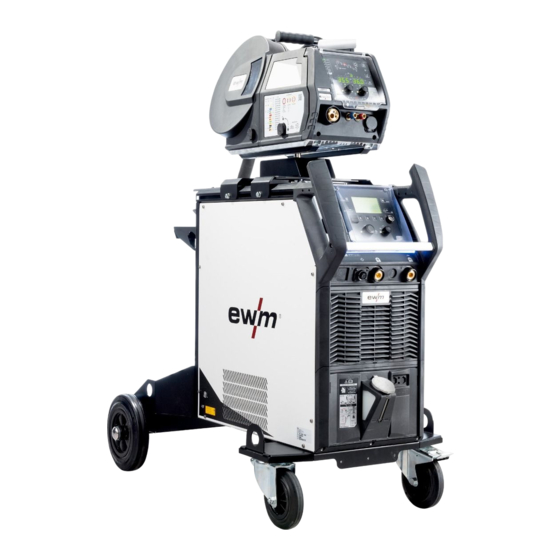
Intended use Use and operation solely with the following machines 3.3.1 Part of the complete documentation This document is part of the complete documentation and valid only in combination with all other parts of these instructions! Read and observe the operating instructions for all system components, especially the safety instructions! The illustration shows a general example of a welding system. -
Page 16: Machine Description - Quick Overview
Machine description – quick overview Front view / rear view Machine description – quick overview Front view / rear view Figure 4-1 099-005664-EW501 22.09.2021... - Page 17 Machine description – quick overview Front view / rear view Item Symbol Description Carrying handle Ready for operation signal light Signal light on when the machine is switched on and ready for operation Main Switch Switching the machine on or off. Cooling air inlet Dirt filter optional >...
-
Page 18: Connection Panel
Machine description – quick overview Front view / rear view 4.1.1 Connection panel Figure 4-2 Item Symbol Description Connection socket - RJ45 - Option Network connection > see 5.7 chapter Connection socket for hand scanner - optional Component identification Xnet > see 5.9 chapter Key button, Automatic cutout Wire feed motor supply voltage fuse (press to reset a triggered fuse) -
Page 19: Design And Function
Design and function Transport and installation Design and function WARNING Risk of injury from electrical voltage! Contact with live parts, e.g. power connections, can be fatal! • Observe the safety information on the first pages of the operating instructions! • Commissioning must be carried out by persons who are specifically trained in handling power sources! •... -
Page 20: Machine Cooling
Design and function Transport and installation 5.1.2 Machine cooling Insufficient ventilation results in a reduction in performance and equipment damage. • Observe the ambient conditions! • Keep the cooling air inlet and outlet clear! • Observe the minimum distance of 0.5 m from obstacles! 5.1.3 Workpiece lead, general CAUTION... - Page 21 Design and function Transport and installation Some wire electrodes (e.g. self-shielding cored wire) are welded using negative polarity. In this case, the welding current lead should be connected to the "-" welding current socket, and the workpiece lead should be connected to the "+" welding current socket. Observe the information from the electrode manufacturer! Figure 5-2 Item Symbol...
-
Page 22: Mains Connection
Design and function Transport and installation 5.1.6 Mains connection DANGER Hazards caused by improper mains connection! An improper mains connection can cause injuries or damage property! • The connection (mains plug or cable), the repair or voltage adjustment of the device must be carried out by a qualified electrician in accordance with the respective local laws or nati- onal regulations! •... -
Page 23: Adjusting The Power Source To The Mains Voltage
Design and function Transport and installation 5.1.6.2 Adjusting the power source to the mains voltage The mains voltage is adapted by replugging the operating voltage plug on the printed circuit board VB xx0 into the power source. The machine can be reconnected between three voltage ranges: 1. -
Page 24: Mains Configuration
Design and function Transport and installation 5.1.6.4 Mains configuration The machine may be connected to: • a three-phase system with four conductors and an earthed neutral conductor • a three-phase system with three conductors of which any one can be earthed, e.g. -
Page 25: Notes On The Installation Of Welding Current Leads
Design and function Transport and installation 5.1.8 Notes on the installation of welding current leads • Incorrectly installed welding current leads can cause faults in the arc (flickering). • Lay the workpiece lead and hose package of power sources without HF igniter (MIG/MAG) for as long and as close as possible in parallel. -
Page 26: Stray Welding Currents
Design and function Transport and installation 5.1.9 Stray welding currents WARNING Risk of injury due to stray welding currents! Stray welding currents can destroy protective earth conductors, damage machines and electronic devices and cause overheating of components, leading to fire. •... -
Page 27: Mig/Mag Welding
Design and function MIG/MAG welding MIG/MAG welding 5.2.1 Connection for workpiece lead Some wire electrodes (e.g. self-shielding cored wire) are welded using negative polarity. In this case, the welding current lead should be connected to the "-" welding current socket, and the workpiece lead should be connected to the "+"... -
Page 28: Connection Of Electrode Holder Or Gouging Torch
Design and function MMA welding or gouging 5.3.3 Connection of electrode holder or gouging torch CAUTION Risk of crushing and burns! When changing stick electrodes there is a risk of crushing and burns! • Wear appropriate and dry protective gloves. •... -
Page 29: Connection Of The Electrode Holder / Gouging Torch Over The Wire Feeder
Design and function MMA welding or gouging 5.3.4 Connection of the electrode holder / gouging torch over the wire feeder Only together with wire feeders and the built-in option of electrode holder connection socket OW MMA. For connection description, see the relevant “Wire feeder” operating instructions. Figure 5-12 Item Symbol Description... -
Page 30: Tig Welding
Design and function TIG welding TIG welding 5.4.1 Connection Figure 5-13 Item Symbol Description Wire feeder Note the additional system documents! Welding torch Observe additional system documents! Connection socket, welding current “–” Workpiece Connection socket, “+” welding current • Insert the cable plug of the welding current lead (intermediate hose package) into the connection so- cket, welding current "-"... -
Page 31: Automation Interface
Design and function Interfaces for automation 5.6.1 Automation interface WARNING No function of the external interrupt equipment (emergency stop switch)! If the emergency stop circuit has been set up using an external interrupt equipment connected to the interface for automated welding, the machine must be configured for this setup. -
Page 32: Network Connection
Design and function Network connection Network connection This accessory component is only available as a “factory-fit option”. The network connection allows the integration of the product into an existing network and exchanging data using the quality-management software Xnet. Some features of the software: •... -
Page 33: Component Identification
Only together with the device control Expert XQ 2.0 in the LAN gateway or LAN/Wi-Fi gateway version. Bar codes predefined in ewm Xnet are recorded with a manual scanner. Component data are retrieved and displayed in the control. These accessory components can be retrofitted as an option > see 9 chapter. -
Page 34: Maintenance, Care And Disposal
Maintenance, care and disposal General Maintenance, care and disposal General DANGER Risk of injury due to electrical voltage after switching off! Working on an open machine can lead to fatal injuries! Capacitors are loaded with electrical voltage during operation. Voltage remains present for up to four minutes after the mains plug is removed. -
Page 35: Maintenance Work, Intervals
A periodic test according to IEC 60974-4 "Periodic inspection and test" has to be carried out. In addition to the regulations on testing given here, the relevant local laws and regulations must also be observed. For more information refer to the "Warranty registration" brochure supplied and our information regarding warranty, maintenance and testing at www.ewm-group.com! 099-005664-EW501 22.09.2021... -
Page 36: Disposing Of Equipment
• Information about returning used equipment or about collections can be obtained from the respective municipal administration office. • In addition to this, returns are also possible throughout Europe via EWM sales partners. 099-005664-EW501 22.09.2021... -
Page 37: Rectifying Faults
Rectifying faults Error messages (power source) Rectifying faults All products are subject to rigorous production checks and final checks. If, despite this, something fails to work at any time, please check the product using the following flowchart. If none of the fault rectification procedures described leads to the correct functioning of the product, please inform your authorised dea- ler. - Page 38 Rectifying faults Error messages (power source) Error (category) Possible cause Remedy Low coolant level low flow rate Fill coolant. Check coolant flow - remove kinks in hose package. Adjust flow threshold. [1] [3] Clean water block. Pump does not turn Turn the pump shaft.
- Page 39 Rectifying faults Error messages (power source) Error (category) Possible cause Remedy 33 Error UIST Voltage recording faulty Eliminate short circuit in welding cir- cuit. remove external sensor voltage. Request service. 34 Electronics error A/D-channel error Switch the machine off and on again. Request service.
-
Page 40: Warnings
Rectifying faults Warnings Error (category) Possible cause Remedy 56 Mains phase failure One phase of the mains voltage Check mains connection, mains plug has failed. and mains fuses. Slave tacho error Wire feeder fault (slave drive). Check connectors, cables, connec- tions. - Page 41 Rectifying faults Warnings Warning Possible cause / remedy 8 Welding circuit The welding circuit inductance is too high for the selected welding task. 9 WF configuration Check WF configuration. 10 Partial inverter One of several partial inverters is not supplying welding current. 11 Excess temperature, coolant Check temperature and switching thresholds.
-
Page 42: Checklist For Rectifying Faults
Rectifying faults Checklist for rectifying faults Warning Possible cause / remedy 40 Mains undervoltage Check supply voltage. 41 Cooling module not recognised Check the cooling unit connection. 47 Battery (Bluetooth remote con- Battery level is low (replace battery) trol) only for XQ machine series See technical data for values and other switching thresholds. - Page 43 Rectifying faults Checklist for rectifying faults Wire feed problems Contact tip blocked Clean and, if necessary, replace. Setting the spool brake Check settings and correct if necessary Setting pressure units Check settings and correct if necessary ...
-
Page 44: Technical Data
Technical data Dimensions and weighte Technical data Performance specifications and guarantee only in connection with original spare and replacement parts! Dimensions and weighte 355 XQ 405 XQ 505 XQ Dimensions (l x b x h) 625 x 298 x 531 mm 24.6 x 11.7 x 20.9 inch Weight 39,4 kg... -
Page 45: Taurus Xq 355 Synergic
Technical data Taurus XQ 355 Synergic Taurus XQ 355 Synergic MIG/MAG Welding current (I 5 A to 350 A Welding voltage according to standard (U 14,3 V to 31,5 V 20,2 V to 34,0 V 10,2 V to 24,0 V Duty cycle DC at 40°... -
Page 46: Taurus Xq 405 Synergic
Technical data Taurus XQ 405 Synergic Taurus XQ 405 Synergic MIG/MAG Welding current (I 5 A to 400 A Welding voltage according to standard (U 14,3 V to 34 V 20,2 V to 36,0 V 10,2 V to 26,0 V Duty cycle DC at 40°... -
Page 47: Taurus Xq 505 Synergic
Technical data Taurus XQ 505 Synergic Taurus XQ 505 Synergic MIG/MAG Welding current (I 5 A to 500 A Welding voltage according to standard (U 14,3 V to 39 V 20,2 V to 40 V 10,2 V to 30 V Duty cycle DC at 40°... -
Page 48: Accessories
Accessories General accessories Accessories Performance-dependent accessories like torches, workpiece leads, electrode holders or intermediate hose packages are available from your authorised dealer. General accessories Type Designation Item no. KLF-L1-L2-L3-PE Label of mains cable 094-023697-00000 DM 842 Ar/CO2 230bar 30l D Pressure regulator with manometer 394-002910-00030 32A 5POLE/CEE... -
Page 49: Coolant - Type Bluecool
Accessories Computer communication 9.5.1 Coolant - type blueCool Type Designation Item no. blueCool -10 5 l Coolant up to -10 °C (14 °F), 5 l 094-024141-00005 blueCool -10 25 l Coolant up to -10 °C (14 °F), 25 l 094-024141-00025 blueCool -30 5 l Coolant up to -30 °C (22 °F), 5 l 094-024142-00005... -
Page 50: Appendix
Appendix Searching for a dealer Appendix 10.1 Searching for a dealer Sales & service partners www.ewm-group.com/en/specialist-dealers "More than 400 EWM sales partners worldwide" 099-005664-EW501 22.09.2021...
Need help?
Do you have a question about the Taurus XQ 355 Synergic and is the answer not in the manual?
Questions and answers