Table of Contents
Advertisement
Advertisement
Table of Contents

Related Manuals for frako RM 9606


Summary of Contents for frako RM 9606
- Page 1 Reactive Power Control Relay RM 9606 Operating Instructions...
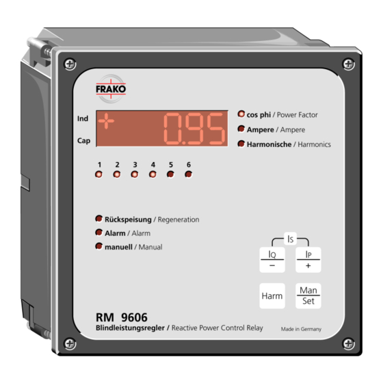
- Page 2 / Manual capacitor stages off manual mode and on manually (also or set-mode Harm to alter preset values during programming RM 9606 operation) Blindleistungsregler / Reactive Power Control Relay Made in Germany Selection button for automatic or manual operation •...
- Page 3 View from below 50/60Hz Alarm 400V~ 250V~ /3A Relay 380V~ /5A max 5A 230V~ S1 S2 Figure 2: View from below...
-
Page 4: Table Of Contents
Contents Page Page Summary of Instructions.... 7 5.8 Number of Contactors used..25 5.9 Specifying fixed Stages ....25 Functions ........8 5.10 ON/OFF Connection Identification26 2.1 Automatic Identification of 5.11 Connection Mode ......26 Voltage and Current Source..8 5.12 Setting Capacitor Discharge Time26 2.2 Automatic Identification of the 5.13 Setting Cyclic/ Connected Capacitor Stages.. - Page 5 Safety and Warning Instructions!! !!! Important, read before commissioning !!! • The user must make sure that every person handling this unit must know these operating instructions and handle the unit accordingly. • These operating instructions must be read thoroughly before the unit is installed and commissioned.
-
Page 7: Summary Of Instructions
If no numbers appear on the display 1. Summary of Instructions then the control relay must be briefly On delivery, the control relay is set to pre- disconnected from voltage programmed standard values. source and the "Set" button has to (see Table 1, pages 15 to 17) be pressed again according to c). -
Page 8: Functions
Resetting of the control relay and re- grammed time delay. identification of voltage and current This causes the RM 9606 to switch ca- sources is initiated by pressing but- pacitor stages onto the power source sup- tons "+" and "Set" simultaneously for ply, as and when required, in order to at least 8 seconds. -
Page 9: Automatic Setting Of Switching Time Delay
2.4 Power Feedback normal operation. However, The RM 9606 is equipped with a four recommend that if capacitor stages are quadrant control. This means that even added at a later date, the set-up procedure when active power is fed back into the be repeated (see section 2.1). -
Page 10: Installation And Connection
3.2 Voltage Connection 3. Installation and Connection The control relay should preferably be The Reactive Power Control RM 9606 connected to the three-phase system as automatically determines the location of shown in (page 11). To keep the function the current and voltage sources (auto- "Zero Voltage Alarm"... -
Page 11: Current Transformer Connection
Figure 3: Circuit Diagram 3.3 Current Transformer Connection Notice: After connection the short-circuiting bridge The outputs S1 and S2 of the current might have to be removed from the cur- transformer are connected to the terminals rent transformer. S1 and S2 of the control relay. In order to keep the load on the current transformer 3.4 Alarm Contacts as low as possible the supply lines should... -
Page 12: Control Contacts
When there is an alarm signal, the LED 3.6 Additional Instructions "alarm" lights up and the relevant LED The installation and connection of the RM begins to flash on the control relay. 9606 is only finished, once it has been installed and wired according to these in- structions. -
Page 13: Commissioning
8 seconds. 4.2 Renewed Commissioning ATTENTION: After a mains failure the control relay If the RM 9606 does not act as de- immediately starts the normal control scribed above, remove voltage source programme again. The data which were and check installation. -
Page 14: Programming (Set)
5. Programming (Set) • The actual value appears on the display In order to permit the widest possible use when the "man/set" is pressed again. of the control relay, multiple settings are available. To simplify matters, the control • By pressing the "+" or "-" button the next relay is set to standard values in our higher or lower setting can be attained. - Page 15 Table 1: Programming of Values Programme Description Pre-programmed Programme Range Mode No. standard Value -01- Target Power Ind. 0.92 from cap. 0.90 to ind. 0.8 in Factor increments of 0.01 steps -02- Parallel Shift PS -1.0 (Target Power from –2 to +4 in increments Factor is lower of 0.5 steps than limit value)
- Page 16 Table 1 Programming of Values Programme Description Pre-programmed Programme Range Mode No. standard Value -10- Automatic ON= automatic identification of OFF= manual voltage and When “ON“, mode -11- can only current source be read but not changed. -11- Enter or read Automatic See Table 2 mode of...
- Page 17 Table 1 Programming of Values Programme Description Pre-programmed Programme Range Mode No. standard Value -18- harmonic From 1 to 20 % in 0.1 % steps or threshold in % 0.5 % steps at high speed.*) -19- harmonic From 1 to 20 % in 0.1 % steps or threshold in % 0.5 % steps at high speed.*) -20-...
- Page 18 If the current transformer is installed in correct direction and the connections S1(k) and S2(l) are correctly connected with the control relay, the following kinds of Connection modes are valid: Connection at the voltage path Connection mode L/N – L L/N –...
-
Page 19: Setting Of Target Power Factor
Regeneration However, if the control relay operates out- Active current Switched off side the band range, the RM 9606 will try to come within the band range with the minimum of switchings. One scale division corresponds to 0.65 *... -
Page 20: Parallel Shift (Ps)
5.2 Parallel Shift (PS) Figure 7: Control response after setting target power factor = 0.92 ind; L = OFF; This setting causes a parallel shift of the PS = -1.0 band range as shown in Figure 4 by the Reactive current set value. - Page 21 The limitation therefore specifies Figure 9: Control response after setting absolute reactive power limit, below which target power factor = 0.92 ind; PS = -1.0; the control band does not go. L = +1.0 Reactive current Figure 8: Control response after setting target power factor = 0.92 ind;...
-
Page 22: Switching Time Delay
5.5 Automatic Stage Current (c/k) Identification "ON/OFF" Active current Regeneration The RM 9606 has an automatic c/k identi- fication, i.e. it calculates the appropriate Switched off response current the first time the control relay is energized. This procedure is re-... -
Page 23: Response Current (C/K)
5.6 Response Current (c/k) The Control Relay RM 9606 calculates a When setting the automatic stage current identification to "OFF" the response cur- control characteristic from the power rent can be set between 0.02 and 2.0 A in factor, the parallel shift and the limitation steps of 0.01 A. - Page 24 Table 3: Response Current at 400V mains voltage (c/k value) c/k-adjustment for mains voltage 400 VAC, 50 Hz ∼ ∼ ∼ ∼ Stage rating of the smallest capacitor bank (not total rating) in kvar Current transformer A /A 2,5 6,25 7,5 12,5 30 /5 0,40 0,80 0,98 1,20 1,60 40 /5 0,30 0,60 0,74 0,90 1,20 1,50...
-
Page 25: Switching Sequence
(switching programme) can be reset to the following combinations capacitor 5.9 Specifying fixed Stages stages: The Control Relay RM 9606 allows the 1:1:1:1:1:1 1:1:2:4:4:4 1:2:3:4:4:4 first three control outputs to be treated as 1:1:2:2:2:2 1:1:2:4:8:8 1:2:3:6:6:6 fixed stages. -
Page 26: On/Off Connection Identification26
15 minutes due to high In order to support the maintenance of the load changes or phase imbalances, it is unit the RM 9606 provides an internal possible to enter the connection mode counter for each switching output. -
Page 27: Reseting Switching Counter
Harmonic Threshold When choosing mode -15- the display shows "0". With the "+" and "-" buttons a The Control Relay RM 9606 has a har- stage number between 1 and 6 or "all" monic monitoring system for the 5 can be chosen. Leaving the programing , and 13 harmonics. -
Page 28: Setting 11 Th Harmonic Threshold
5.22 Harmonic Over-Current Alarm range the alarm signal functions as well. Signal When setting "OFF" the alarm is sup- The Control Relay RM 9606 is able to pressed. determine the ratio between the actually measured RMS current and the nominal 5.24 Total kvar Display... -
Page 29: Operation
6. Operation 6.1 Modes of Display switched off and if there is no change in The power factor display is independent of the measured current, all remaining the control relay operation and can be stages are switched off and "I=0" appears reprogrammed at any time. -
Page 30: Manual Operation
6.1.3 Active Current portion is displayed and must be multiplied by the CT ratio to obtain the actual value. Press "IQ", "IP", or "Harm" buttons to exit the display. The display shows the active current on 6.1.5 Harmonics (5 - 13 the fundamental oscillation in the current transformer (CT) -
Page 31: Alarms
When the "+" button is pressed once, In manual mode, the programmed switch- "1.ON" appears on the display until the ing off time (discharge time) is taken into control relay has switched on the first consideration, i.e. when switching on a stage after approx. - Page 32 6.3.1 Power Factor Alarm After the alarm has been acknowledged it If the threshold values set for "switch-on" takes approx. 4 minutes until the neces- and "switch-off" are exceeded and no fur- sary capacitor stages are switched on ther change can take place in the output again.
-
Page 33: Technical Data
7. Technical Data At the same time, the alarm contact Mode of Connection: closes and the "Alarm" LED lights up for Phase/Phase connection or as long as there is no voltage applied to Phase/Neutral connection the measurement input terminals of the Current via current transformer in optional control relay. - Page 34 Loading Capacity of the Control Fastening: Contacts: Through the front panel by means of a Switching voltage: screwdriver 380 VAC (acc. to VDE 0110 part B) Front Panel Dimensions: 250 VAC (acc. to VDE 0110 part C) 144 x 144 mm (to DIN 43 700) Switching current up to 5 A max.
-
Page 35: Trouble-Shooting
8. Trouble-Shooting Pos. Faults Possible Causes Necessary Action Control relay does not There is either no voltage or Check whether the correct operating function, digital display the wrong voltage has been voltage is applied to the control relay. remains blank. applied to the control relay. - Page 36 Pos. Faults Possible Causes Necessary Action Despite inductive load When programming the Check programming of the control no stages are switched control relay, the c/k factor, relay and change if necessary. on when relay is in switching time delay, or automatic mode.
- Page 37 Notice:...
- Page 38 Reactive Power Control Relay RM 9606 Sales Programme Power capacitors for low voltage Power factor correction systems Power factor correction systems with reactors Modules for power factor correction systems Active filters Dynamic compensation of harmonics Reactive power control relays Maximum demand control systems...
Need help?
Do you have a question about the RM 9606 and is the answer not in the manual?
Questions and answers