Table of Contents
Advertisement
Quick Links
- 1 Table of Contents
- 2 Commissioning and Maintenance
- 3 System Location - Correct Installation, Ingress Protection and Room Temperature
- 4 Current Transformer - Selection, Correct Arrangement and Connections
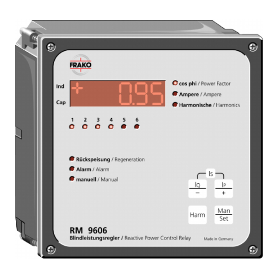
- 5 Reactive Power Control Relays: Rm 9606, Rm 2106, Rm 2112, Emr 1100 S and Emr 1100 - Automatic Detection of Connection, Switching Sequence and Response Current, No-Volt Release, Etc
- 6 Operation and Maintenance - Monitoring of Fuses, Contactors Screwed Connections, Etc
- 7 Troubleshooting - a Tabular Guide to Troubleshooting any Problems Arising During Commissioning
- 8 Circuit Diagram
- Download this manual
Advertisement
Table of Contents


Need help?
Do you have a question about the STR Series and is the answer not in the manual?
Questions and answers