Table of Contents
Advertisement
Quick Links
Advertisement
Table of Contents
Troubleshooting

Related Manuals for frako RM 2106/12


Summary of Contents for frako RM 2106/12
- Page 1 Reactive Power Control Relay RM 2106/12 Operating Instructions...
- Page 3 Safety and warning notices !!! Important !!! Read this before commissioning!!! • The operating instructions should be read carefully before the device is assembled, installed and put into operation. • Installation and commissioning should only be carried out by appropriate specialists in accordance with existing regula- tions and provisions.
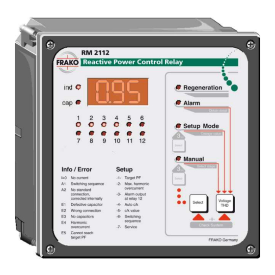
- Page 4 Figure 1: Front view a Display for active capacitor stages f LED lights up in setup mode g LED lights up in manual mode b Display for inductive or capacitive operating status h Multifunctional button c Digital display (see operating instructions) d LED indicates regenerative power i Selection key for manual mode, setup mode or automatic mode...
- Page 5 Figure 2: Rear view j Connection for the current trans- m Connectors for the control contacts former that switch the contactors. shared pole is connected to terminal k Optional connector for improved ´L´. measurement of harmonic wave n Typical connection l Connector for power supply to the control relay...
-
Page 6: Table Of Contents
Contents Page Page Introduction .........7 Functioning and operation ..23 1.1 How to use 5.1 Automatic control mode ....23 these operating instructions ...7 5.2 Displaying the 1.2 Scope of functions ......7 total harmonic distortion factor ..23 5.3 Check System ......23 Installation and connection..8 5.4 Manual mode...... -
Page 7: Introduction
1.2 Scope of functions 1. Introduction Below is a brief overview of the various The reactive power control relay RM functions of the device: 2112 and RM 2106 respectively is capa- • 12 switching contacts at RM 2112 and ble of measuring the reactive power and 6 switching contacts at RM 2106 active power of the connected mains •... -
Page 8: Installation And Connection
2.2 Voltage connection 2. Installation and connection Reactive power control relay obtains its reactive power control relay voltage supply via terminals ”L” and ”N” RM 2112 and RM 2106 respectively can (see figure 2, item ’l’). be connected in a number of different A phase conductor is to be connected to ways. -
Page 9: Meas" Measuring
2.5 Switching contacts It is permissible for connector S1 or S2 of The shared pole of all switching contacts the current transformer to be grounded. (Figure 2, item ’m’) is connected to ter- minal ”L” of the voltage supply. Caution: Important information: The nominal current in the current transformer path may not exceed 5 A. -
Page 10: Standard Connection
RM2112 / 06 Figure 3: Single phase connection 2.7 Single phase connection The connection diagram above shows This connection variant can be chosen if the same connection as the one printed the above-mentioned harmonics are suf- on the back of the control relay. ficient for monitoring overcurrent or if overcurrent monitoring has been com- The voltage signal for power factor meas-... -
Page 11: Extended Connection
RM2112 / 06 Figure 4: Extended connection 2.8 Extended connection This type of connection offers a more dU/dt measuring procedure can be used precise measuring procedure for the for calculating the overcurrent. overcurrent in the capacitor. This means that all frequencies up to the In this case, the terminal ”Meas”... -
Page 12: Connection With Voltage Transformer
RM2112 / 06 Figure 5: Connection with control transformer 2.9 Connection with voltage transformer The connection diagram above shows conductors, connection must be as how the control relay is connected shown in the diagram. The measuring together with a control transformer. procedure then is similar to that for the extended connection (see section 2.8). -
Page 13: Connection In Special Cases
RM2112 / 06 Figure 6: Connection in special cases 2.10 Connection in special cases For all types of connections (figure 3 to 6) The type of connection shown above should be used if the voltage between it is also possible to connect the current the phase conductors does not exceed transformer in phase conductors L2 or 240VAC. -
Page 14: Start-Up
3. Start-up After installation has been carried out as Important information: described in section 2, the control relay can be started. The device should always be switched off before carrying out wiring or installation activities. Important information: (For help in troubleshooting see Make sure that the connector termi- section 6.) nals of the control relay are no longer... -
Page 15: Subsequent Start-Up
3.2 Subsequent start-up In such cases the entire control system is to be switched off and the error must be The control relay begins with its normal eliminated. regulatory program immediately after a (For troubleshooting see section 6.) power failure. In some circumstances the control relay If the ”Select”... -
Page 16: Control Relay Setup
4. Control relay setup This means that the user mostly only A wide range of setting options are pro- vided to enable the reactive power con- needs to change the target power factor. trol relay to be used in the widest possi- The setup mode can be reached from ble way. -
Page 17: Target Power Factor Setting
The procedure for checking or repro- If no key is pressed for about 15 minutes, gramming the setting values is as fol- setup mode is quit automatically. lows: 4.1 Target power factor setting -1- The required target power factor can be set between 1.00 and ind. - Page 18 relay will not carry out any further large or small zero preceding the decimal switching. point in the target power factor input. For a target power factor of 1.00 this The type of control band shown in figure means that the permitted reactive power 8 can be achieved by means of a large may not exceed 0.65 times the lowest zero preceding the decimal point of the...
-
Page 19: Overcurrent Switch Off
If generators are active in mains parallel Note: mode, even small amounts of inductive This function should be set to OFF when choked capacitor stages are reactive powers are unwanted in the used. mode of regenerative power. In such cases the target power factor should be set with a small zero preceding 4.3 Switching contact as the decimal point (see Figure 9). -
Page 20: Automatic Response Current Identification
4.4 Automatic response current identification -4- determined can be read under setup If set to On the control relay operates code -5- but cannot be altered. with the response current determined at initial start-up and the values determined When automatic response current identi- fication is switched off (-4-), the response for the switch outputs. - Page 21 Response current-setting 400 VAC mains voltage Current- Step size (= Rating of smallest stage kvar) transformer A /A 2,5 6,25 7,5 12,5 30 /5 0,40 0,80 0,98 1,20 1,60 40 /5 0,30 0,60 0,74 0,90 1,20 1,50 50 /5 0,24 0,48 0,59 0,72 0,96 1,20 1,44 60 /5 0,20 0,40 0,49 0,60 0,80 1,00 1,20 1,60 75 /5 0,16 0,32 0,39 0,48 0,64 0,80 0,96 1,28 1,60 1,92 100 /5 0,12 0,24 0,30 0,36 0,48 0,60 0,72 0,96 1,20 1,44 1,92...
-
Page 22: Relative Value Of The Switch Outputs
4.6 Relative value of the switch outputs -6- The flashing LED in the stage display (a) These values refer to the relative stage ratings. indicate the switch output to which the relative value refers. Pressing the ”Se- Example: lect”key (i) briefly allows you to skip to A system has the following stages: the next relative value. -
Page 23: Functioning And Operation
5. Functioning and operation activated, the control relay also checks The control relay runs completely auto- matically after it has been connected and the power of the capacitors connected. started. The current power factor appears The control relay issues an alarm in the in the digital display (c). -
Page 24: Manual Mode
Note: Note: The check system mode defines the No automatic switching activities are present stage ratings as reference val- carried out in manual mode. Manual subsequent stage rating mode does not terminate automati- checking. cally. (see section 3) Alarm signals E4 and E5 are also gener- ated in manual mode, but do not lead to any switching activities. -
Page 25: Alarms And Troubleshooting
6.1.2 E1 - Defect capacitor stages 6. Alarms and troubleshooting Possible causes: The control relay has a number of ways • individual capacitor stages only have of identifying connection errors and func- 2-phase connections to the mains tional errors. • the defect capacitor stages do not draw a symmetrical current from the 6.1 Connection errors 3 phases... -
Page 26: Connection Messages
6.2 Connection messages 6.3 Alarms in automatic control operation In addition to the error messages, the The ”Alarm” LED (e) lights up for as long control relay also displays the results of its automatic connection recognition. as an alarm is active. If alarm output was Messages A1 and A2 can be acknowl- activated on contact 6 of the RM 2106 edged by pressing any key or are auto-... -
Page 27: E5 - Target Power Factor
6.3.2 E5 - Target power factor not 6.3.4 U = 0 - No measuring voltage reached This message indicates that the control If the operating point of the control relay relay with connected ”Meas” terminal has is above the control band (see section been put into operation, however no volt- 4.1) and if all available capacitor stages age can be measured at this input at pre-... -
Page 28: Troubleshooting
7. Troubleshooting Fault Possible causes Necessary action Control relay not work- No or the wrong voltage Check that operating voltage ing; no displays on the has been applied to the applied to the control relay is front of the control relay. control relay. -
Page 29: Technical Data
Fault Possible causes Necessary action "I=0" flashes on the Current transformer line Check current in current path using ammeter (Imin ≥ 0.02 A). display. interrupted or short- circuited. Displayed power Error in the control circuit. Check for the contactors factor is less than to be energized. - Page 30 Panel hole size: No-voltage trip (undervoltage monitoring): 138 x 138 mm (DIN 43 700) With voltage drops under 170 V for more Installation depth: than 10 ms all capacitor stages con- 40 mm nected are switched off. After voltage is Weight: restored the control relay switches the approx.
- Page 31 Notes: BA V1.11; ab SW V1.00...
- Page 32 Reactive Power Control Relay Model RM 2106/12 Sales Programme Power capacitors for low voltage Power factor correction systems Power factor correction systems with reactors Modules for power factor correction systems Active filters Dynamic compensation of harmonics Reactive power control relays...
Need help?
Do you have a question about the RM 2106/12 and is the answer not in the manual?
Questions and answers