
Related Manuals for frako RM 2106


Summary of Contents for frako RM 2106
- Page 1 Reactive Power Control Relay RM 2106 / 2112 Operating Instructions zavoshelectric.ir...
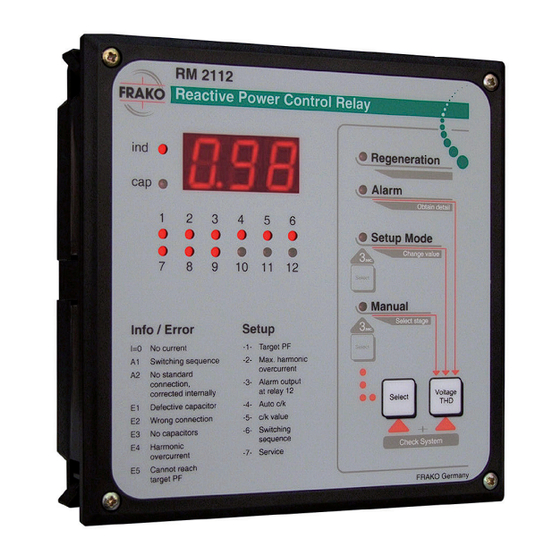
- Page 2 Display for inductive or capacitive LED lights up in manual mode operating status Multifunctional button Digital displays (see operating instructions) LED indicates regenerative power Selection key for manual mode, setup Display for current or historical alarms mode or automatic mode RM 2106 / 2112...
- Page 3 zavoshelectric.ir Figure 2 Rear view Connection for the current transformer m Connectors for the control contacts that Optional connector for improved switch the contactors. The shared pole measurement of harmonic wave is connected to terminal ´L´. Connector for power supply to the Typical connection control relay...
- Page 4 RM 2106 / 2112...
-
Page 5: Table Of Contents
Table of Contents zavoshelectric.ir Introduction Automatic response current How to use these operating identification -4- instructions Response current -5- Scope of functions Relative value of the switch outputs -6- Installation and connection Service -7- Installation Functioning and operation Voltage connection Current transformer connection Automatic control mode Displaying the total harmonic... - Page 6 6.3.2 E5 - Target power factor not reached zavoshelectric.ir 6.3.3 E1 - Defect capacitor stages 6.3.4 U = 0 - No measuring voltage 37 I = 0 - No measuring current Other errors Trouble-Shooting Technical Data RM 2106 / 2112...
- Page 7 Safety and Warning Notices. zavoshelectric.ir Important ! Read this before commissioning ! ■ The operating instructions should be read carefully before the device is assembled, installed and put into operation. ■ Installation and commissioning should only be carried out by appropriate specialists in accordance with existing regulations and provisions ■...
- Page 8 RM 2106 / 2112...
-
Page 9: Introduction
The reactive power control relay RM 2112 control relay. Troubleshooting information is and RM 2106 respectively is capable of also provided there. measuring the reactive power and active Scope of functions power of the connected mains network. - Page 10 RM 2106 / 2112...
-
Page 11: Installation And Connection
The reactive power control relay RM 2112 and RM 2106 respectively can be connected Voltage connection in a number of different ways. The main connection methods are described below. Reactive power control relay obtains its voltage supply via terminals ”L”... -
Page 12: Current Transformer Connection
When the switching contacts are switched, the same voltage is applied as is used to supply This terminal ”Meas” (Figure 2, item ’k’) is not voltage to the control relay (connection ”L”). used in the standard connection. RM 2106 / 2112 zavoshelectric.ir... -
Page 13: Alarm Contact
Switching contact 12 at RM 2112 (switching supply voltage of the control relay. If a floating contact 6 at RM 2106) can be used either as potential contact is required, use an additional a control output for a capacitor stage or as an contactor relay. -
Page 14: Single Phase Connection
The terminal ”Meas” is not in use. Either L1, L2 or L3. In this connection variant, only the 5th, 7th, 11th and 13th harmonics of the voltage are used to calculate the harmonic overcurrent in the capacitor. RM 2106 / 2112 zavoshelectric.ir... -
Page 15: Extended Connection
Figure 4 Extended connection Extended connection two phase conductors to which the capacitors are also connected, the dU/dt measuring This type of connection offers a more precise procedure can be used for calculating the measuring procedure for the overcurrent in overcurrent. -
Page 16: Connection With Voltage Transformer
The control voltage of the transformer may control transformer. not exceed 240 V AC. If the voltage signal is tapped by the control transformer between two phase conductors, RM 2106 / 2112 zavoshelectric.ir... -
Page 17: Connection In Special Cases
connection must be as shown in the diagram. If the control transformer taps the voltage The measuring procedure then is similar to signal between a phase conductor and that for the extended connection (see section neutral, the terminal ”Meas” must remain 2.8). - Page 18 If the control relay operates with automatic response current recognition, connection errors would be reported. If response current recognition is deactivated, then an error in the connection will lead functional errors during subsequent operation. RM 2106 / 2112 zavoshelectric.ir...
-
Page 19: Start-Up
Start-up It may be that the device has already been used and behaves as described in section 3.2. After installation has been carried out as described in section 2, the control relay can If the measuring process is not complete be started. -
Page 20: Subsequent Start-Up
The programmed control parameters are for each stage after about 15 seconds or can stored in a non-volatile memory and can be be acknowledged earlier by pressing any key. altered as necessary. (see chapter 4) RM 2106 / 2112 zavoshelectric.ir... -
Page 21: Maintenance
Maintenance With maintenance of the power factor correction system, also the function of the control relay should be checked. The control relay may be cleaned only with a dry cloth. Important information: The control relay should be disconnected from the mains while cleaning the back of the control relay. - Page 22 RM 2106 / 2112 zavoshelectric.ir...
-
Page 23: Control Relay Setup
Control relay setup A wide range of setting options are provided This means that the user mostly only needs to enable the reactive power control relay to change the target power factor. to be used in the widest possible way. To simplify matters the control relay is set to The setup mode can be reached from any of standard values in the factory (see table 1... - Page 24 ”-1-” then appears on the display. This ■ The control relay returns to automatic number (setup code) shows which regulatory mode if the ”Select” key is variable is displayed and/or changed held down (approx. 3 seconds). (see Table 1). RM 2106 / 2112 zavoshelectric.ir...
-
Page 25: Target Power Factor Setting -1
Note: In this setting the control relay attempts During ”setup mode”, no controlling to minimize reactive power irrespective of activities are carried out by the control active power. relay. The control relay creates a tolerance band (or If no key is pressed for about 15 minutes, control band) around its target (in this case setup mode is quit automatically. - Page 26 If generators are active in mains parallel power factor setting. mode, even small amounts of inductive reactive powers are unwanted in the mode of regenerative power. RM 2106 / 2112 zavoshelectric.ir...
-
Page 27: Overcurrent Switch Off -2
However, a capacitive power factor in this case is Contact 6 of the RM 2106 device or contact prefered to even small amounts of inductive 12 of the RM 2112 device can be used to issue reactive power. -
Page 28: Automatic Response Current Zavoshelectric.ir
The response current describes the width = Current transformer ratio (primary/ of the control band (see figures 7 to 9). The secondary current) greater the value, the broader the control band. = Voltage transformer ratio (primary/ secondary voltage) (if any) RM 2106 / 2112 zavoshelectric.ir... - Page 29 Response current setting 400 V AC mains voltage Current Step size (= Rating of smallest stage kvar) transfor- 6.25 12.5 30/5 0.40 0.80 0.98 1.20 1.60 40/5 0.30 0.60 0.74 0.90 1.20 1.50 50/5 0.24 0.48 0.59 0.72 0.96 1.20 1.44 60/5 0.20...
-
Page 30: Relative Value Of The Switch Outputs -6
0.0. Only whole numbers can be entered as are sorted according to reactive power factors. (capacity), then the power difference between two consecutive combinations may not be more than 1.2 times the smallest stage power. RM 2106 / 2112 zavoshelectric.ir... -
Page 31: Service -7
Service -7- The fundamental wave currents presently flowing in the current path (j) of the control relay and be displayed under this point. The display for inductive or capacitive operating status (b) can be used to determine which current is displayed. ind. - Page 32 RM 2106 / 2112 zavoshelectric.ir...
-
Page 33: Functioning And Operation
Functioning and operation identification is activated, the control relay also checks the power of the capacitors connected. The control relay runs completely automatically after it has been connected and started. The The control relay issues an alarm in the event current power factor appears in the digital of an error. -
Page 34: Manual Mode
An exception to this is the alarm contact when alarm output is activated on contact 6 Manual mode of the RM 2106 device or contact 12 of the RM 2112 device (setup code -3-). Pressing ”Select” (i) for more than 3 seconds switches the control relay to manual mode. -
Page 35: Alarms And Troubleshooting
Alarms and troubleshooting (including PFC) (see connection diagrams 3 to 6). The control relay has a number of ways of identifying connection errors and functional In this case the reactive power control system errors. must be set out of operation and the error has to be eliminated. -
Page 36: I = 0 - No Current In Current Path
If alarm output was or are automatically acknowledged after a activated on contact 6 of the RM 2106 device waiting period of about 30 seconds. or contact 12 of the RM 2112 device (setup code -3-), this contact also closes. -
Page 37: E4 - Harmonic Overcurrent In The Capacitor
6.3.1 E4 - Harmonic overcurrent in the volatile memory (only when automatic response capacitor current identification is active; setup code -4-). The control relay issues this alarm if the If the control relay detects a drop in stage rating programmed limiting value for the ”harmonic during operation of more than 20% or there is overcurrent”... - Page 38 This signal does not activate an alarm. Other errors Situations may arise due to the connection or special operating conditions that cannot be identified by the control relay. Table 3 below lists further sources of errors. RM 2106 / 2112 zavoshelectric.ir...
- Page 39 Trouble-Shooting Pos. Fault Possible causes Necessary action Control relay not wor- No or the wrong voltage Check that operating voltage king; no displays on the has been applied to the applied to the control relay is at front of the control relay control relay the right level The control relay does...
- Page 40 Set the response current correctly switch off all stages at set too high according to Table 1 or Formula 1 light load or standstill Press the „Select“ key (i) Control relay in manual mode Table 3 Notes on troubleshooting RM 2106 / 2112 zavoshelectric.ir...
- Page 41 Maximum 264 V AC at terminal ”N” Indicator elements: RM 2106: 12 LEDs Control Contacts: RM 2112: 18 LEDs RM 2106: 6 switching contacts 3 character digital display RM 2112: 12 switching contacts with potential binding to supply voltage Operating temperature range: (terminal „L“)
- Page 42 Art.No. 20-50014 Weight: approx. 0.8 kg Installation position: as required Connections: Terminal block cable cross section max. 1.5 mm Protection class: Terminal block IP 20 Housing IP 54 (when the sealing ring is used) RM 2106 / 2112 zavoshelectric.ir zavoshelectric.ir...
Need help?
Do you have a question about the RM 2106 and is the answer not in the manual?
Questions and answers