Advertisement
Quick Links
These operating instructions are delivered with each product.
Malfunctions, damage or injury may occur if these instructions are not
followed.
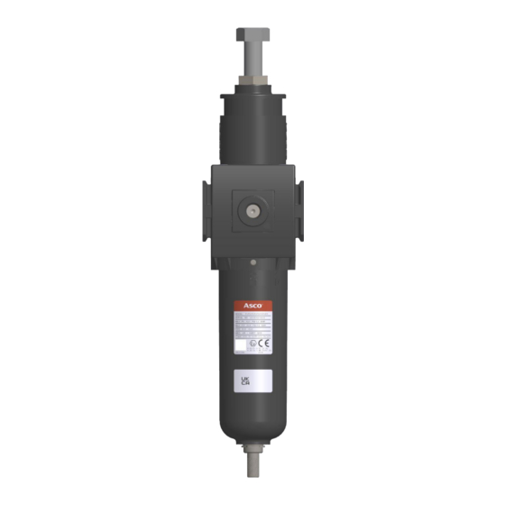
Description
Series 642 Air Filter Regulators are designed for use in potentially explosive
atmospheres caused by gases, vapors, mists and/or dusts as per ATEX Directive
2014/34/EU and standards EN ISO 80079-36. UKSI Regulation 2016 : 1107 (as
amended by UKSI 2019:696)- Annex 3A, Part 1 after ATEX directive and BS
EN ISO 80079-36 (2016)
Classification (Zone 1 and 21): II 2 G Ex h IIC T5 Gb, II 2 D Ex h IIIC T5 Db
The Classification temperature depends on the ambient temperature. These
regulators are made of external metal parts & internal with plastic/metal parts.
Startup and maintenance are to be performed as detailed below.
General
This component is not a safety accessory. It is intended only for the compliant
use either as an individual component or incorporated in an apparatus,
machinery and installations. Filter Regulators are designed to be operated in
accordance with the limits specified in the nameplate or as specified in this
document. All applicable directives, legislations, orders and standards, as
amended from time to time, as well as state-of-the-art practices and procedures
must be observed for intended scope of application of the product. Where
applicable take all appropriate measure to ensure the requirements are met. This
device complies with the essential safety requirements of the EU PED
2014/68/EU. Declaration of conformity is available on request.
All assembly, operation, use and maintenance must be performed by
qualified, authorized personnel. Personnel working with the components must
be familiar with the applicable safety and regulations relating to the components,
apparatus and machinery installations. In case of problems, please contact
ASCO or one of its authorized representatives in your region.
General Operating Specifications
Fluid: Instrument air
Ambient Temperature: For manual drain: the temperature range should be within
-40 C to + 90 C (-40F to +194F); For Auto drain: the range should be within
+1°C to + 80°C (34°F to +176°F).
Inlet Pressure: Do not exceed the maximum operating pressure 20 bar(290psi)
for manual drain FR, 17bar(247psi) for auto drain FR.
Installation
Check the preliminary storage conditions required for the component. They must
be in accordance with the product's specifications.
Carefully remove the Filter Regulator from the packaging.
Power off and depressurize the apparatus, machinery or installation designed to
receive the FR.
Install the FR near where the air is to be used.
Install ASCO pressure gauge comes accessory on the gauge port. & Do Not
modify the device.
Make sure that the fluid is compatible with the materials it contacts.
Operator or user must ensure that the gas group corresponds to the product's
classification.
Check Nameplate for correct catalog number, pressure, temperature and service.
Never apply incompatible fluids or exceed pressure rating of the regulator.
The installer must install the air filter regulator at the user's location in
accordance with the requirements specified in Directive 99/92/EC.
Positioning
For optimum life and performance, the FR should be mounted
vertically upright (Max. Inclination 5°).
ASCO NUMATICS INDIA Pvt Ltd.,
Plot No P45, 8th Avenue, Mahindra world city
Chengalpattu, Kanchipuram
Tamil nadu- 603002, India
INSTALLATION AND MAINTENANCE INSTRUCTIONS
ALUMINIUM FILTER REGULATOR
SIZE: 1/4" & 1/2"
Piping
Connect piping to valve according to markings on FR body. Apply pipe
compound sparingly to male pipe threads only. If applied to FR threads, the
compound may enter the FR and cause functional difficulty. Avoid pipe strain
by properly supporting and aligning piping. When tightening the pipe, do not
use the FR as a lever. Locate wrenches applied to piping as close as possible to
connection point.
Direct Frontal mounting or mounting with brackets possible.
Maintenance
NOTE: Ensure the air supply is completely stopped. It is not necessary to remove
the FR from the pipeline for repairs.
Cleaning
All FRs should be cleaned periodically. The time between cleanings will
vary depending on the medium and service conditions. The most common part
that requires cleaning is the filter element.
Use running water for regular cleaning or a mild detergent for cleaning the
filter element. Do not use diluted acids, strong detergents or corrosive chemicals.
For auto drain version clean the filter ring periodically.
Causes of Improper Operation
Incorrect pressure: Check upstream pressure. Pressure to FR must be within
range specified on nameplate.
Excessive Leakage: Disassemble FR and clean all parts. If parts are worn or
damaged, install a complete ASCO Spare Parts kit.
Manual drain operation:
Hold the knurling face of drain with fingers & rotate it to the anti-clockwise
direction looking from top to unscrew the manual drain to purge out the water
that accumulated in the bowl. After draining out, screw the manual drain back
to its original position & ensure proper working of AFR.
Earthing:
The earth is connected to the unit or to the combination of conditioning units by
the downstream and upstream use of metal pipes connected to the earth. If the
pipes are non-conductive, earth connection should be performed by the assembly
and/or fixing devices adapted to the ATEX products.
Automatic draining:
Auto drain provides hassle free draining of equipment which purge out the water
accumulated in the bowl automatically. It also provides manual drain feature
integrated with automatic drain. Anti-clockwise to drain & clockwise to close
drain when looking from top view.
FORM NO: 551462-001
REV:
AC
ECN:
326819
: 1
PAGE NO
SERIES
642
Advertisement

Related Manuals for Emerson Asco 642 Series


Summary of Contents for Emerson Asco 642 Series
- Page 1 INSTALLATION AND MAINTENANCE INSTRUCTIONS SERIES ALUMINIUM FILTER REGULATOR SIZE: 1/4” & 1/2” Piping These operating instructions are delivered with each product. Malfunctions, damage or injury may occur if these instructions are not Connect piping to valve according to markings on FR body. Apply pipe followed.
- Page 2 INSTALLATION AND MAINTENANCE INSTRUCTIONS SERIES ALUMINIUM FILTER REGULATOR SIZE: 1/4” & 1/2” FR DISASSEMBLY Disassemble FR in an orderly fashion using exploded views for identification and placement of parts. Refer to figure 1. Remove bowl from the body (as shown in fig. 17) and the remove bowl seal Unscrew the filter assembly by hand itself Carefully unscrew the bowl baffle in filter assembly and remove...
- Page 3 INSTALLATION AND MAINTENANCE INSTRUCTIONS SERIES ALUMINIUM FILTER REGULATOR SIZE: 1/4” & 1/2” DIAPHRAGM SUPPORT BOLT(*) PLATE LOCK NUT DIAPHRAGM 6.8±2 Nm (60±2 IN/LBS) 4x SCREW, PLATE UNDER BONNET DIAPHRAGM O-RING(*) BONNET DISC O-RING(*) SPRING GAUGE PORT STEM(*) DIAPHRAGM ASSEMBLY POPPET ASSEMBLY(*) SIDE COVER LIP SEAL(*)
- Page 4 INSTALLATION AND MAINTENANCE INSTRUCTIONS SERIES ALUMINIUM FILTER REGULATOR SIZE: 1/4” & 1/2” TECHNICAL DETAILS TEMP, STANDARD, NBR (°C) -40 TO +90 TEMP, FKM (°C) -20 TO +80 TEMP, LOW TEMP (°C) TEMP, AUTO DRAIN (°C) +1 TO +80 FIG. 4: LABEL FIG.
- Page 5 INSTALLATION AND MAINTENANCE INSTRUCTIONS SERIES ALUMINIUM FILTER REGULATOR SIZE: 1/4” & 1/2” MOUNTING FIG. 6: DISASSEMBLED VIEW FIG. 5: ASSEMBLED VIEW GAUGES FIG. 8: WITH SS GAUGE FIG. 9: NON-SS GAUGE FIG. 7: WITHOUT GAUGE ASCO NUMATICS INDIA Pvt Ltd., FORM NO: 551462-001 Plot No P45, 8th Avenue, Mahindra world city REV:...
-
Page 6: Tamper Proof
INSTALLATION AND MAINTENANCE INSTRUCTIONS SERIES ALUMINIUM FILTER REGULATOR SIZE: 1/4” & 1/2” TAMPER PROOF ASSEMBLY (FIG 11) FINAL ASSEMBLY (FIG 10) DIS ASSEMBLY (FIG 12) LOCKING PROVISION FIG. 13 FIG. 14: PARTIAL SECTIONAL VIEW ASCO NUMATICS INDIA Pvt Ltd., FORM NO: 551462-001 Plot No P45, 8th Avenue, Mahindra world city REV: Chengalpattu, Kanchipuram... - Page 7 INSTALLATION AND MAINTENANCE INSTRUCTIONS SERIES ALUMINIUM FILTER REGULATOR SIZE: 1/4” & 1/2” T- HANDLE T – HANDLE TYPE REGULAR CLOCKWISE TO SET PRESSURE (FROM TOP VIEW) FIG. 16 FIG. 15 ASCO NUMATICS INDIA Pvt Ltd., FORM NO: 551462-001 Plot No P45, 8th Avenue, Mahindra world city REV: Chengalpattu, Kanchipuram ECN:...
- Page 8 INSTALLATION AND MAINTENANCE INSTRUCTIONS SERIES ALUMINIUM FILTER REGULATOR SIZE: 1/4” & 1/2” ASSEMBLY DISASSEMBLY F – FRONT VIEW FIG. 18 FIG. 17 ASCO NUMATICS INDIA Pvt Ltd., FORM NO: 551462-001 Plot No P45, 8th Avenue, Mahindra world city REV: Chengalpattu, Kanchipuram ECN: 326819 Tamil nadu- 603002, India...
- Page 9 INSTALLATION AND MAINTENANCE INSTRUCTIONS SERIES ALUMINIUM FILTER REGULATOR SIZE: 1/4” & 1/2” METAL • TEMPERATURE: -40°C ... +90°C MANUAL • Min. INLET PESSURE (P1 Min.): 0 Bar DRAIN • Max. INLET PRESSURE (P1 Max.): 20 Bar (Brass/stainless steel) 10-32 UNF •...
- Page 10 INSTALLATION AND MAINTENANCE INSTRUCTIONS SERIES ALUMINIUM FILTER REGULATOR SIZE: 1/4” & 1/2” 642 SERIES ATEX USABLE IN ATEX ZONES FIG. A ASCO NUMATICS INDIA Pvt Ltd., FORM NO: 551462-001 Plot No P45, 8th Avenue, Mahindra world city REV: Chengalpattu, Kanchipuram ECN: 326819 : 10...
- Page 11 INSTALLATION AND MAINTENANCE INSTRUCTIONS SERIES ALUMINIUM FILTER REGULATOR SIZE: 1/4” & 1/2” SCREW (1), BOWL (2), BODY (3), BONNET (4), DRAIN (5), AND BOLT (6) ALL ARE METAL PARTS FIG. B ASCO NUMATICS INDIA Pvt Ltd., FORM NO: 551462-001 Plot No P45, 8th Avenue, Mahindra world city REV: Chengalpattu, Kanchipuram ECN:...
- Page 12 INSTALLATION AND MAINTENANCE INSTRUCTIONS SERIES ALUMINIUM FILTER REGULATOR SIZE: 1/4” & 1/2” This product category does not fall within the scope of the ATEX 2014/34 / EU directive: the risk analysis according to the EN ISO 80079-36 standard has shown that no potential source of ignition specific to the products are effective. These products can be used in specific explosion zones 1 and 21 in compliance with our installation instructions: * List of affected components •...
Need help?
Do you have a question about the Asco 642 Series and is the answer not in the manual?
Questions and answers