
Summary of Contents for Yeswelder TIG-225P
- Page 1 TIG-225P IGBT INVERTER MULTI-PROCESS DC TIG WELDER (HF TIG, LIFT TIG, PULSE TIG, COLD SPOT TIG, STICK) Jan, 2022...
-
Page 3: Table Of Contents
MACHINE GROUNDING ......................07 INPUT CONNECTION ........................08 INPUT FUSE AND SUPPLY WIRE ....................08 INPUT VOLTAGE .........................08 OUTPUT CONNECTIONS ......................08 CONNECTION DIAGRAMS FOR THE TIG-225P ................09 OPERATION............................10 CASE FRONT & BACK CONTROLS ...................10 USER INTERFACE CONTROLS ....................11 PROCESS, OUTPUT CONTROL ....................11 2-STEP FUNCTIONALITY, OUTPUT ON ..................12 4-STEP FUNCTIONALITY, OUTPUT ON ..................12... -
Page 4: Safety
SAFETY... - Page 5 SAFETY Read and understand the following safety highlights. For additional safety information, it is strongly recommended you download free PDF of Standard ANSI Z49.1 from the American Welding Society. https://www.aws.org/library/doclib/AWS-Z49-2021.pdf...
- Page 6 SAFETY...
- Page 7 SAFETY...
-
Page 8: Installation
INSTALLATION TECHNICAL SPECIFICATIONS: TIG-225P INPUT-SINGLE PHASE ONLY Standard Voltage/Frequency Input Current max=42.5A, I leff=32.7A 220V±10% 50/60Hz max=45A, I leff=34.8A 110V±10% 50/60Hz RATED OUTPUT – DC ONLY Voltage Mode Duty Cycle Current Volts at Rated Current 225A GTAW 100% 174A 220V 225A SMAW 100% 174A 155A 16.2V GTAW 100% 120A 14.8V... -
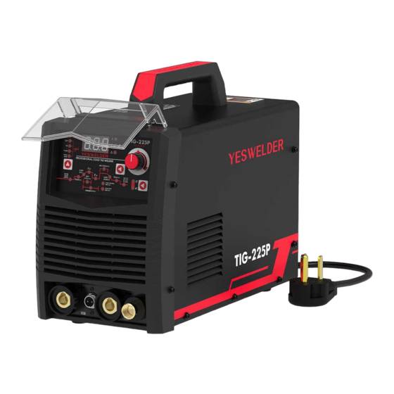
Page 9: Included Components
INSTALLATION INCLUDED COMPONENTS 1. TIG-225P TIG Welder 5. 220V-110V Adapter 2. Work Clamp 6. WP-17V TIG Torch with Consumables 3. Electrode Holder 7. WP-9 TIG Torch with Consumables 4. Gas Hose 8. Foot Pedal... -
Page 10: Safety Precautions
INSTALLATION... -
Page 11: Input Connection
INSTALLATION FIGURE 1... -
Page 12: Connection Diagrams For The Tig-225P
INSTALLATION WORK CLAMP WORK CLAMP... -
Page 13: Operation
OPERATION (See Figure 2) (See Figure 3) FIGURE 2 FIGURE 3 User Interface - For selecting process and Input Power Cord parameters Power Switch - Controls power to the Control Knob - Used to control machine machine output amperage and sequencer setting Gas Inlet - Shielding gas connects to this Twist - Mate Work Connector - For inlet... -
Page 14: User Interface Controls
OPERATION FIGURE 4 (See Figure 5) FIGURE 5 1. Stick 2. Lift TIG 3. High-Frequency TIG 4. Pulse TIG 5. Cold Spot TIG Amperage Display - Displays the current amperage and sequencer setting Status Lights - Power on, thermal fault, voltage fault, internal fault (See Figure 6) Control Knob - Used to set output current and to... -
Page 15: 2-Step Functionality, Output On
OPERATION (See Figure 10) FIGURE 10 FIGURE 7 FIGURE 8 FIGURE 9... -
Page 16: Sequencer Functions, Pulse Sequencer Functions
OPERATION FIGURE 12 FIGURE 11 FIGURE 13 COLD SPOT FUNCTIONS... -
Page 17: Setup Menu Stick Welding (Smaw)
OPERATION Select the output current I with sequencer control button, turn the control knob to meet the needs of the job. Higher amps for thicker material, lower amps for thinner material. FIGURE 15 Electrode Holder Work Clamp Specify your Arc Force setting, the Arc Force increases temporary the output current, used to clear intermittent connections between the electrode and the weld puddle that occur during... -
Page 18: Safety Precautions
OPERATION Very little routine maintenance is necessary to keep your TIG-225P running in top condition. No specific schedule can be set for performing the following items; factors such as hours of usage and machine environment should be considered when establishing a maintenance schedule. -
Page 19: Troubleshooting
TROUBLESHOOTING Observe all Safety Guidelines detailed throughout this manual Error Description Possible Cause Course of Action Code Overheating Input voltage too high Machine internal failure Output Abnormal Input voltage too low Temperature controller failure Machine internal failure Machine internal failure Over-current... - Page 20 Adjust flow rate Contaminated gas or leaks in gas line, Check gas line & connections torch, or connections Faulty Components, PC Boards or Contact YESWELDER Output shut off during welding Connections support@yeswelder.com Observe all Safety Guidelines detailed throughout this manual...
- Page 21 Blow out machine with clean, dry low Dirt and dust may have clogged the Thermal light turns on pressure air cooling channel inside machine Contact YESWELDER Faulty fans or connections support@yeswelder.com Contact YESWELDER Faulty Components, PCB or support@yeswelder.com Connections No gas &...
-
Page 22: Wiring Diagram
WIRING DIAGRAM... - Page 23 www.YesWelder.com...
Need help?
Do you have a question about the TIG-225P and is the answer not in the manual?
Questions and answers