Table of Contents
Advertisement
Advertisement
Table of Contents

Subscribe to Our Youtube Channel
Related Manuals for KSB Calio SI Dual


Summary of Contents for KSB Calio SI Dual
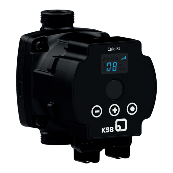
- Page 1 Circulator for OEMs Calio SI Dual / Calio SI Therm Installation/Operating Manual...
- Page 2 Legal information/Copyright Installation/Operating Manual Calio SI Dual / Calio SI Therm Original operating manual All rights reserved. The contents provided herein must neither be distributed, copied, reproduced, edited or processed for any other purpose, nor otherwise transmitted, published or made available to a third party without the manufacturer's express written consent.
-
Page 3: Table Of Contents
Commissioning/Start-up/Shutdown.................... 23 Commissioning/Start-up .......................... 23 6.1.1 Prerequisites for commissioning/start-up .................. 23 6.1.2 Priming and venting the pump...................... 23 6.1.3 Start-up............................... 24 Operating limits.............................. 25 6.2.1 Ambient temperature........................ 25 6.2.2 Minimum inlet pressure........................ 25 6.2.3 Maximum operating pressure ...................... 25 Calio SI Dual / Calio SI Therm 3 of 50... - Page 4 Trouble-shooting.......................... 44 Related Documents .......................... 45 10.1 Sectional drawing with list of components .................... 45 10.2 Standards and technical codes / directives.................... 46 EU Declaration of Conformity ...................... 47 Index .............................. 48 Calio SI Dual / Calio SI Therm 4 of 50...
-
Page 5: Glossary
Machine without drive, additional components or accessories Pump set Complete pump set consisting of pump, drive, additional components and accessories Suction lift line/suction head line The pipeline which is connected to the suction nozzle Calio SI Dual / Calio SI Therm 5 of 50... -
Page 6: General
The name plate indicates the type series and size as well as the main operating data. They uniquely identify the pump (set) and serve as identification for all further business processes. In the event of damage, immediately contact your nearest KSB service facility to maintain the right to claim under warranty. 1.2 Target group This operating manual is aimed at the target group of trained and qualified specialist technical personnel. -
Page 7: Key To Safety Symbols/Markings
Warning about hot surfaces In conjunction with one of the signal words this symbol indicates a hazard involving hot surfaces. Calio SI Dual / Calio SI Therm 7 of 50... -
Page 8: Safety
▪ Observe all safety information and instructions in this manual. ▪ Never exceed the permissible application and operating limits specified in the data sheet or product literature regarding pressure, temperature, etc. Calio SI Dual / Calio SI Therm 8 of 50... -
Page 9: Personnel Qualification And Training
▪ If stopping the pump does not increase potential risk, fit an emergency-stop control device in the immediate vicinity of the pump (set) during pump set installation. Calio SI Dual / Calio SI Therm 9 of 50... -
Page 10: Safety Information For Maintenance, Inspection And Installation
Never operate the pump (set) outside the limits stated in the data sheet and in this manual. The warranty relating to the operating reliability and safety of the supplied pump (set) is only valid if the equipment is used in accordance with its intended use. Calio SI Dual / Calio SI Therm 10 of 50... -
Page 11: Transport/Storage/Disposal
1. On transfer of goods, check each packaging unit for damage. 2. In the event of in-transit damage, assess the exact damage, document it and notify KSB or the supplying dealer and the insurer about the damage in writing immediately. -
Page 12: Return To Supplier
Contact your local waste disposal partner for returns. If the used electrical or electronic equipment contains personal data, the operator is responsible for deleting it before the equipment is returned. Calio SI Dual / Calio SI Therm 12 of 50... -
Page 13: Description Of The Pump (Set)
1 Type series, size 7 Current input 2 Mains voltage, frequency 8 Pressure class 3 Thermal class 9 Temperature class 4 Enclosure 10 Energy efficiency index EEI To EN 16297-3 Calio SI Dual / Calio SI Therm 13 of 50... -
Page 14: Design Details
▪ Vent function ▪ Deblocking the rotor Signalling functions and display functions ▪ Alternating display of flow rate, head and electrical input power ▪ Error messages on the display To EN 16297-3 Calio SI Dual / Calio SI Therm 14 of 50... -
Page 15: Configuration And Function
(3). In the flow passage of the pump casing (1) the kinetic energy of the fluid handled is converted into pressure energy. The fluid handled is pumped to the discharge nozzle, where it leaves the pump set. Calio SI Dual / Calio SI Therm 15 of 50... -
Page 16: Noise Characteristics
▪ Pump set 4.10 Accessories ▪ Sealing elements ▪ Two-piece thermal insulation shell ▪ Power cable 230 V (length: 1 m / 2 m / 3 m) ▪ Control cable 230 V (length: 0.5 m / 1 m / 2 m / 3 m) Calio SI Dual / Calio SI Therm 16 of 50... -
Page 17: Installation At Site
Calio SI Dual pump used for drinking water or foodstuff applications Danger of poisoning! ▷ Never use Calio SI Dual pumps for drinking water applications or foodstuff applications. ▷ For drinking water applications and foodstuff applications only use the pump type Calio SI Therm. -
Page 18: Installing The Pump Set
The direction of flow of a vertically installed pump should be upwards. NOTE Do not install the pump at the lowest point of the system to prevent any impurities from collecting in the pump. Calio SI Dual / Calio SI Therm 18 of 50... - Page 19 4. Tighten the pipe union hand-tight with a suitable tool. 5. Accurately insert the sealing element in the opposite pipe union. 6. Tighten the pipe union hand-tight with a suitable tool. Calio SI Dual / Calio SI Therm 19 of 50...
-
Page 20: Connecting The Piping
ü The piping has been anchored in close proximity to the pump and connected without transmitting any stresses or strains. 1. Thoroughly clean, flush and blow through all vessels, piping and connections (especially of new installations). Calio SI Dual / Calio SI Therm 20 of 50... -
Page 21: Enclosure/Insulation
Only the power cables included in the scope of supply must be used for connecting the pump. Only use power cables specified by the manufacturer in the event of defects. Remove power cables and/or plugs with a suitable tool. Calio SI Dual / Calio SI Therm 21 of 50... -
Page 22: Connecting The Electric Cables
ü The pump set has been de-energised and secured against unintentional start-up. 1. Connect the power cable to the connection provided. 2. Connect the control cable for external input (PMW signal or analog signal 0 - 10 V) to the connection provided. Calio SI Dual / Calio SI Therm 22 of 50... -
Page 23: Commissioning/Start-Up/Shutdown
2. During operation at maximum speed loosen the vent plug with a suitable tool until some of the fluid handled escapes. 3. Tighten the vent plug to a maximum tightening torque of 0.5 Nm. 4. Repeat the procedure until all air has escaped. Calio SI Dual / Calio SI Therm 23 of 50... -
Page 24: Start-Up
1. Fully open the shut-off element in the suction head line / suction lift line. 2. Close or slightly open the shut-off element in the discharge line. 3. Start up the motor. Calio SI Dual / Calio SI Therm 24 of 50... -
Page 25: Operating Limits
CAUTION Permissible operating pressure exceeded Damage to connections and seals! ▷ Never exceed the operating pressure specified in the data sheet. The maximum operating pressure is 10 bar. In the boiler Calio SI Dual / Calio SI Therm 25 of 50... -
Page 26: Fluid Handled
▷ Only operate the pump (set) within the temperature limits indicated. Table 9: Temperature limits of the fluid handled Permissible fluid temperature Value Maximum +110 °C Minimum -10 °C The fluid temperature has an impact on the minimum inlet pressure. (ð Section 6.2.2, Page 25) Calio SI Dual / Calio SI Therm 26 of 50... -
Page 27: Shutdown/Storage/Preservation
For returning the equipment to service, observe the sections on commissioning/start- up (ð Section 6.1, Page 23) and the operating limits (ð Section 6.2, Page 25) . In addition, carry out all servicing/maintenance operations before returning the pump (set) to service. (ð Section 8, Page 41) Calio SI Dual / Calio SI Therm 27 of 50... -
Page 28: Operation
Display shows the head. Constant-pressure Control operating mode ▪ Symbol lights up when this operating mode is active. Proportional-pressure Control operating mode ▪ Symbol lights up when this operating mode is active. Calio SI Dual / Calio SI Therm 28 of 50... -
Page 29: Operating Modes
The setting of the head setpoint depends on the piping curve of the system and on the heat requirements. As standard the pump set is pre-set to Proportional-pressure Control (Δp-v) operating mode. Calio SI Dual / Calio SI Therm 29 of 50... -
Page 30: Constant-Pressure Control
Step 4: Confirming the current setpoint ▪ Press and hold the control button (●) for a minimum of 3 seconds. – The set setpoint flashes and is saved. Fig. 7: Constant-pressure Control settings Calio SI Dual / Calio SI Therm 30 of 50... -
Page 31: Proportional-Pressure Control
(+) or (-) respectively. Step 4: Confirming the current setpoint ▪ Press and hold the control button (●) for a minimum of 3 seconds. – The set setpoint flashes and is saved. Calio SI Dual / Calio SI Therm 31 of 50... -
Page 32: Open-Loop Control Mode
Step 4: Confirming the current setpoint ▪ Press and hold the control button (●) for a minimum of 3 seconds. – The set setpoint flashes and is saved. Fig. 10: Open-loop Control settings Calio SI Dual / Calio SI Therm 32 of 50... -
Page 33: Ecomatch
– 1 = EcoMatch enabled Step 4: Saving EcoMatch ▪ Press and hold the control button (●) for a minimum of 3 seconds. – The set status flashes and is saved. Calio SI Dual / Calio SI Therm 33 of 50... -
Page 34: Operation Controlled By External Input
AN = analog signal 0 - 10 V Step 4: Confirming the current setpoint ▪ Press and hold the control button (●) for a minimum of 3 seconds. – The set setpoint flashes and is saved. Calio SI Dual / Calio SI Therm 34 of 50... - Page 35 ▪ Calculated flow rate [m ▪ Fault status for dry running and blocked rotor X [%] Fig. 12: PWM profile A, PWM signal from pump control system to external control system H Head X PWM Calio SI Dual / Calio SI Therm 35 of 50...
- Page 36 Table 19: Speeds depending on the size Size Speed Minimum Maximum [rpm] [rpm] 15-50-130 3080 25-50-130 3080 25-50-180 3080 15-70-130 3650 25-70-130 3650 25-70-180 3650 15-80-130 4000 25-80-130 4000 25-80-180 4000 30-80-180 4000 Calio SI Dual / Calio SI Therm 36 of 50...
- Page 37 ▪ Calculated flow rate [m ▪ Fault status for dry running and blocked rotor X [%] Fig. 14: PWM profile C, PWM signal from the pump to the external control system H Head X PWM Calio SI Dual / Calio SI Therm 37 of 50...
- Page 38 Table 22: Speeds depending on the size Size Speed Minimum Maximum [rpm] [rpm] 15-50-130 3080 25-50-130 3080 25-50-180 3080 15-70-130 3650 25-70-130 3650 25-70-180 3650 15-80-130 4000 25-80-130 4000 25-80-180 4000 30-80-180 4000 Calio SI Dual / Calio SI Therm 38 of 50...
- Page 39 Table 23: Speeds depending on the size Size Speed Minimum Maximum [rpm] [rpm] 15-50-130 3080 25-50-130 3080 25-50-180 3080 15-70-130 3650 25-70-130 3650 25-70-180 3650 15-80-130 4000 25-80-130 4000 25-80-180 4000 30-80-180 4000 Calio SI Dual / Calio SI Therm 39 of 50...
-
Page 40: Functions
Excessive temperature Alarm Pump stops. Overcurrent Alarm Pump stops. Internal fault Alarm Pump stops. Blocked rotor Alarm Pump stops. Voltage error Alarm Pump stops. Motor fault Alarm Pump stops. Calio SI Dual / Calio SI Therm 40 of 50... -
Page 41: Servicing/Maintenance
▷ Observe all legal regulations on the disposal of fluids posing a health hazard. 1. Flush and clean the pump before transporting it to the workshop. 2. Provide a certificate of decontamination for the pump. Calio SI Dual / Calio SI Therm 41 of 50... -
Page 42: Removing The Pump Set From The Piping
▷ Keep the assembly area clean. ▷ Keep a safety distance of at least 0.3 m from electronic components. WARNING Hot surface Risk of injury! ▷ Allow the pump set to cool down to ambient temperature. Calio SI Dual / Calio SI Therm 42 of 50... - Page 43 2. Disconnect the discharge nozzle and suction nozzle from the piping. 3. Depending on the pump size / motor size, remove the supports from the pump set. 4. Remove the complete pump set from the piping. Calio SI Dual / Calio SI Therm 43 of 50...
-
Page 44: Trouble-Shooting
▪ Vent the system and the pump. (ð Section 6.1.2, Page 23) ▪ Pump running dry ▪ Prime the pump. (ð Section 6.1.2, Page 23) Release pump set pressure before attempting to remedy faults on parts which are subjected to pressure. Calio SI Dual / Calio SI Therm 44 of 50... -
Page 45: Related Documents
10.1 Sectional drawing with list of components 81-59 Fig. 17: Sectional drawing Table 26: List of components Part No. Description Part No. Description Volute casing Copper winding Impeller Plain bearing Pump rotor 81-59 Stator Calio SI Dual / Calio SI Therm 45 of 50... -
Page 46: Standards And Technical Codes / Directives
RoHS Directive 2015/863/ RoHS Directive 2017/2102/ Regulation No. 1907/2006 of the European Parliament and of the Council of REACH Regulation 18 December 2006 concerning the Registration, Evaluation, Authorisation and 1907/2006 Restriction of Chemicals (REACH) Calio SI Dual / Calio SI Therm 46 of 50... -
Page 47: Eu Declaration Of Conformity
Ankara, 1 January 2020 Coskuner, Evren Head of Research and Development KSB Pompa Armatür San. ve Tic. A.Ş. Seker Mah. Fatih Sultan Mehmet Bulv. 451/A TR-06930 Ankara Factory Where applicable Calio SI Dual / Calio SI Therm 47 of 50... -
Page 48: Index
Fluid handled Density 26 Installation at site 17 Intended use 8 Key to safety symbols/markings 7 Operating limits 25 Operating modes 14 Other applicable documents 6 Piping 20 Preservation 11, 27 Product description 13 Return to supplier 12 Returning to service 27 Calio SI Dual / Calio SI Therm 48 of 50... - Page 50 KSB Pompa Armatür San. Ve Tic. A.Ş. Şeker Mahallesi Fatih Sultan Mehmet Bulvari 451/A 06790 Etimesgut/Ankara (Turkey) Tel: +90 312 280 8640 www.ksb.com.tr...
Need help?
Do you have a question about the Calio SI Dual and is the answer not in the manual?
Questions and answers