Table of Contents
Advertisement
Quick Links
Advertisement
Table of Contents

Related Manuals for Flow Controller Systems FCS KA-DISP


Summary of Contents for Flow Controller Systems FCS KA-DISP
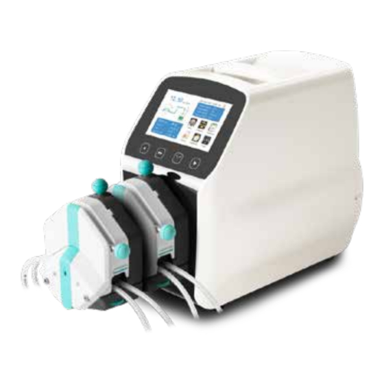
- Page 1 FCS KA-DISP Dispensing Pump Operation Manual...
- Page 2 Note: Please read the manual carefully before operating the product. Warning: Tubing may crack due to wear and results in the leak of fluid from tubing. This can result in bodily harm to the user or damage to equipment. Inspect the tubing frequently and change tubing before cracks or damage occurs.
-
Page 3: Table Of Contents
Catalogue 1. Product Introduction ..................- 4 - 2. Product Appearance ................... - 4 - 3. Keyboard Instruction ..................- 5 - 4. Operation Interface Structure ................- 6 - 5. Main Functions Operation Process ..............- 18 - 6. External Control Interface Instructions .............- 20 - 7. -
Page 4: Product Introduction
1. Product Introduction The KA-DISP series product is a flow measurement type intelligent peristaltic pump. It has a 4.3-inch color touch screen control, uses an animated working state visual with flow data, allowing the setting of parameters and system settings in the same screen. -
Page 5: Keyboard Instruction
3. Keyboard Instruction Stop Button Full Button CW/CCW Button Start Button Stop Button: Pressing the stop button stops the pump from working. Locked buttons in the main interface can be used. Full Button: When in stopping state or transferring state, press this button so ... -
Page 6: Operation Interface Structure
4. Operation Interface Structure Main Interface System Calibrat Date&T Dispensin Volume Timing Settings Configu Back Commu External External nication Control ration Suction Speed KA-DISP Series Operation Interface Instruction 4.1 Booting Interface After powering on the system, it will enter the welcome interface, click anywhere or wait for 2.5 seconds and it will enter the English main operation interface automatically. - Page 7 Speed/Flow Rate Display: In flow rate mode, displays the current flow rate, and the motor speed is displayed at the C frame. In speed mode, displays the current set up speed and flow rate is displayed at the C frame. Click A to amend the flow rate or speed.
- Page 8 4.3 Numeric Keypad Input Interface Numeric keypad input interface as below: Input information Input data Display unit display display 800.00 Flow mL/min Backspace Unit Return Confirm Unit:Unit switch Input digital area Clr:Clear input Input Information Display: The information displayed is the current operation object. Input Data Display: Display the current input data, range is 0.01-9999.
- Page 9 4.4 The Basic Configuration Interface The basic configuration interface: Pump Head Reference Flow Rate EasyPumpI Max:1999.00 mL/min Tubing Size Min:333.29 uL/min Flow Rate Speed Cancel Click the pump head and tubing size to choose the pump head and tubing. Reference flow rate displays the maximum and minimum flow rate with the current pump head and tubing.
- Page 10 4.5 Back Suction Angle Interface The back suction angle interface as below: ! Please enter back Back suction angle suction angle range: 0-360° 360.00 degree Setting the back suction angle can prevent the liquid from dropping when the motor stops when transferring the liquid with viscosity in the tubing.
- Page 11 4.6 External Setting Interface External Setting Interface as below: External Control Signal Ext.Start/Stop Pulse Foot Pedal Setting Ext.CW/CCW Click System Settings button in the main interface, then click External Control to enter External Settings interface. There are two types of signals for external control motor start/stop and direction: Level mode and Pulse mode.
- Page 12 4.7 External Speed Control Setting Interface External Speed Control Setting Interface as below: Analog signal selection ON/OFF 0-5V Work speed limit 0V corresponds to the speed 0.0/ 600.00 5V corresponds to the speed 600.00 Click System Settings button in the main interface, then click External Speed Control button to enter External Speed Control Settings interface.
- Page 13 4.8 Communication Setting Interface Click System Settings button in the main interface, then click Communication button to enter Communication Settings interface. This pump supports MODBUS-RTU Mode. Please select baud rates and communication interface (RS485/RS232). Click Slave No. button to enter peristaltic pump address No.
- Page 14 4.9 Flow Rate Calibration Interface Flow Rate Calibration Interface as below: Actual Vol. Volume adjust Fixed time 0.0000ml +0.0000ml and volume Volume Test 10.00 Run Time 1.00 1.00 Reset The top left corner displays the function. When fixed volume measurement is turned on, it displays fixed volume.
- Page 15 After you finish the tests, the actual volume area displays the average data. Click the CAL button and a prompt shows the calibration is successful. If you need higher accuracy, you can click Add and Dec button to micro adjust the flow rate to reach high accuracy transferring and dispensing.
- Page 16 In this interface, you can set the current date and time, and it will display at the top right corner. Click Set Date button. A Set year numeric keypad will pop up. The range of the year is 1970-2099. After you set up the year, then set the month and date. Click Set Time button and a numeric keypad will pop up.
- Page 17 4.12 Dispensing Interface Dispensing Interface as below: Fixed volume Runing time Repeat times 1.00 0002 Set volume Suspend time 600.00 1.00 Fixed time and volume function turned on, flow rate is 300.00mL/min, speed is 103.44rpm After turning on this function, the pump will enter dispensing mode. Peristaltic pump transfers fixed volume in fixed time.
-
Page 18: Main Functions Operation Process
5. Main Functions Operation Process 5.1 Flow Rate Transferring Function Note: Please refer to the flow rate calibration interface instructions for the flow rate calibration process. 5.2 Fixed Volume Measurement Function Note: Please refer to the flow rate calibration interface instructions for the flow rate calibration process. - Page 19 5.3 Dispensing Boot into Back to the main inter- the main face after finish interface calibration, click start key start working Click the System settings button, choose pump head Display the The pump display the current and tubing size, choose dynamic The set up volume volume and countdown time,...
-
Page 20: External Control Interface Instructions
Click Start Time. Set the start time to 8:30 a.m. Turn the button ON. Click Custom. The repeat date window will pop up, as below: Monday Friday Tuesday Saturday Wednesday Sunday Thursday 6. External Control Interface Instructions External control interface as below:... - Page 21 0-10V ② 0-5V ⑥ ① 4-20mA I-/V- ③ CW/CCW ⑦ R/S 2 R/S 1 ④ OUT1 ⑤ OUT2 ① Analog signal input terminal: Choose External speed control signal and turn on the Ext. Speed in the external control settings interface to control the motor speed from 0 rpm to maximum speed through analog signal.
- Page 22 CW/CCW: External control direction signal input R/S 2: External control start/stop signal input Set up the external control mode in the settings interface. Turn on the corresponding external control function to make the external control signal active. ④ R/S 1 External control signal input terminal: Passive signal input. The passive switch or foot pedal switch can be connected with the terminal.
- Page 23 motor to stop running. In Pulse mode: Short connect K4 for the motor to run at full speed. Disconnect it for the motor to stop. ⑤ The motor working status output terminal: Output motor working status as below: If connecting with relays, when the motor runs, K1 connects. When the motor stops running, the K1 disconnects.
- Page 24 ⑦ RS485 Communication Interface: Choosing RS485 communication settings interface makes this terminal active. GD1: RS485 signal ground A+: Connect RS485 A+ terminal B-: Connect RS485 B- terminal Note: No matter whether you choose RS232 or RS485, the communication protocol is standard MODBUS protocol.
-
Page 25: Technical Specification
7. Technical Specification AC 220V±10% Power 50Hz/60Hz (standard) Flow rate resolution 0.01ml/min supply AC 110V±10% 50Hz/60Hz (optional) Touch screen and External Operation mode Switch signal mechanical keypad control Passive switching signal: 0-5V, 0-10V, 4-20mA External Foot pedal switch External control speed for option control Active switching signal: 5-... - Page 26 KA-DISP 1-III, KA- DISP 3-III, KA-DISP <80W 6-III KA-DISP 1, KA-DISP 1-II, KA-DISP 3, KA- Stepper motor DISP 3-II, KA-DISP 6 Motor type KA-DISP 1-III, KA- DISP 3-III, KA-DISP Closed loop stepper motor 6-III Temperature 0-40℃ Humidity <80%...
-
Page 27: Function And Features
8. Function and Features 4.3 inch color touch screen control: Animation shows working state. The flow volume and motor speed are displayed on the same screen. Intelligent calibration function: It can calibrate the flow rate and dispensing volume, ensure the flow accuracy, and is suitable for high accuracy transferring liquid. -
Page 28: Dimension Drawing
9. Dimension Drawing Unit: (mm) 9.1 Single pump head YZ1515x pump head MC pump head... - Page 29 AMC pump head EasyPump pump head 9.2 KA-DISP series product...
- Page 30 KA-DISP +YZ15 pump head Note: For each additional pump head in series, the longitudinal dimension shall be increased by 55mm. KA-DISP + MC pump head Note: For each additional channel, the longitudinal dimension shall be increased by 10mm.
- Page 31 KA-DISP + AMC pump head Note: For each additional channel, the longitudinal dimension shall be increased by 10mm. KA-DISP+EasyPump pump head Note: For each additional pump head in series, the longitudinal dimension shall be increased by 61mm.
-
Page 32: Maintenance
10. Maintenance Check the running status of machine before starting it. Normal operation can be put into use. Check for leakage and correct fault if it appears. Clean liquid overflowed from the pump as soon as possible. Please turn off the power supply and unplug the power socket (hold the socket ... -
Page 33: Warranty And After-Sales Service
Electrical surge as a cause of failure is excluded. Chemical attack is excluded. Improper operation or man-made damage as a cause of failure is excluded. Flow Controller Systems 2950 Buskirk Ave Suite 300 Walnut Creek CA 94597 Tel: 925-516-4459 Website: flowcontrollersystems.com Email: justin@fcs-us.net...
Need help?
Do you have a question about the FCS KA-DISP and is the answer not in the manual?
Questions and answers