Table of Contents
Advertisement
Quick Links
Advertisement
Table of Contents

Related Manuals for ROOTECH ACCURA 5500


Summary of Contents for ROOTECH ACCURA 5500
- Page 1 User Guide[English] Revision 1.03 2018/03/15...
- Page 2 ◼ During normal operation of the Accura 5500S meter, hazardous voltages are present on its terminal strips. ◼ Standard safety precautions are followed while performing any installation or service work[removing PT fuses, shorting CT secondaries, etc]. ◼ Do not access to terminal strips of the Accura 5500 meter after installation. Page 2...
- Page 3 Warning Observe the following instructions, or permanent damage to the meter may occur. ◼ Do not apply Accura 5500 to voltages and currents that exceed input ratings of PT and CT. Manual Rootech Inc. reserves the right to make changes in the device specifications shown in this User Guide without notice.
- Page 4 Warranty For products and software that are sold or licensed by Rootech Inc. during the period from the date of receipt by you until the present, Rootech warrants only to the original purchaser. The purchased products shall be substantially free from material defects in material and workmanship by Rootech for two years from the date receipt by you.
- Page 5 ◼ If the original identify markings(trade-mark, serial number, etc) have been defaced, altered, or removed Rootech shall not be liable for any other claim than a claim solely for the breach of one of the above warranties that is made in accordance with the above described procedures- made by the original purchaser, its employees, agents, or contractors for any loss, damage, or expense incurred due to, caused by, or related to any purchased product.
- Page 6 Standard Compliance QMS-1347 KAB-QC-09 Page 6...
- Page 7 Revision History The following versions of the Accura 5500 User’s Guide have been released. Revision # Revision date Description Revision 1.00 2009. 08. 10 Initial draft Revision 1.01 2009. 08. 28 1st function added Revision 1.02 2010. 03. 05 2nd function added Revision 1.03...
-
Page 8: Table Of Contents
Contents Chapter 1 Introduction ......................11 Features ..........................11 Applications .......................... 13 Ditigal protection relay system ..................13 Energy management system ..................13 Demand management system requirements in the field ..........13 Power quality analysis system ..................13 Online monitoring/control ..................... 13 Parameters .......................... - Page 9 Meter Menu Display ......................28 Scope Menu Display ......................30 Phase Menu Display ......................31 Harmonics Menu Display ...................... 32 Event Menu Display ....................... 33 Setup Menu Display ......................35 APPENDIX A Specification ....................... 47 APPENDIX B Standard ......................48 APPENDIX C Accuracy/ Reliability ...................
- Page 10 Figures Fig 2.1 Front Side ......................16 Fig 2.2 Rear Side ......................16 Fig 2.3 Side ........................16 Fig 2.4 Panel Cutting Size ....................16 Fig 2.5 Mounting ......................17 Fig 2.6 Typical Wiring (3PT, 3CT) ..................18 Fig 2.7 Typical Wiring Diagram(3P3W, 2PTs: Open-Delta) ..........19 Fig 2.8 Rear Terminal Diagram ..................
-
Page 11: Chapter 1 Introduction
Chapter 1 Introduction Features Item Standard Accura 5500 Measurement Sampling/cycle Maximum 1024[Normal 128] Frequency 50/60Hz Voltage, current, power, frequency, power factor ■ Ground voltage[V ], neutral current[I ■ Demand, Peak demand ■ Maximum, minimum ■ Energy kWh/kVARh received, kWh/kVARh delivered IEC62053-22 Class 0.2S... - Page 12 Waveform capture: voltage, current, digital input Up to recent 100 event logs status Waveform capture resolution, sampling/cycle 128[transient event log: 1024] max/min log ■ Outage protection ■ Touch screen: 7” WVGA Color TFT LCD Vector diagram, harmonic graph ■ oscilloscope: voltage 4channes, current 4channels ■...
-
Page 13: Applications
Applications Digital protection relay system Energy management system Demand management system requirements in the field Power quality analysis system Online monitoring/control Page 13... -
Page 14: Parameters
Parameters † Realtime Average Total Maximum Minimum Phase voltage ■ ■ ■ ■ Line to line voltage ■ ■ ■ ■ Current ■ ■ ■ Power Active ■ ■ ■ Reactive ■ ■ ■ † Apparent ■ ■ ■ Energy Active ■... -
Page 15: Chapter 2 Mounting
Chapter 2 Mounting Environmental Conditions The Accura 5500 should be mounted in a dry, dirt free location away from heat sources and very high electric fields. To operate properly and effectively, environmental conditions should range within the following guidelines Items... -
Page 16: Before You Begin
Before You Begin Before installing the meter, observe the instructions in this guide and read the safety precautions presented on the “Installation Considerations” page. Danger Power up after the voltage and current wiring is completed. Meter Overview Fig 2.1 Front Side Fig 2.2 Rear Side Fig 2.3 Side Fig 2.4 Panel Cutting Size... -
Page 17: Meter Mounting
Meter Mounting Fig 2.5 Mounting Page 17... -
Page 18: Voltage/Current Input Wiring
Voltage/current Input Wiring Wiring diagram[3PTs, 3CTs] Fig 2.6 Typical Wiring (3PT, 3CT) Page 18... -
Page 19: Wiring Diagram[3 Phase 3 Wire: 2Pt Open-Delta]
Wiring diagram[3 phase 3 wire: 2PT Open-delta] Fig 2.7 Typical Wiring Diagram(3P3W, 2PTs: Open-Delta) Page 19... -
Page 20: Rear Terminal
Rear terminal Fig 2.8 Rear Terminal Diagram Control Power: PP, PN ◼ DC 100V ~ 300V ◼ AC 85 ~ 265V Frame Ground: G ◼ Connected to earth terminal Page 20... -
Page 21: Cb Status Input
◼ Phase R: I1S, I1L ◼ Phase S: I2S, I2L ◼ Phase T: I3S, I3L ◼ Neutral: IGS, IGL ◼ Zero sequence current: IZS, IZL ◼ V1, V2, V3, VG, VN CB Status Input ◼ CBN, CBNG CB ON Output ◼... -
Page 22: Digital Input
Digital Input ◼ DI 1 : DI1, DIG ◼ DI 2 : DI2, DIG ◼ DI 3 : DI3, DIG ◼ DI 4 : DI4, DIG ◼ DI 5 : DI5, DIG ◼ DI 6 : DI6, DIG ◼ DI 7 : DI7, DIG ◼... -
Page 23: Chapter 3 Meter Operation/Setup
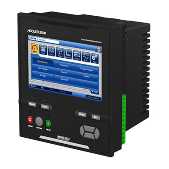
Chapter 3 Meter Operation/Setup Front Panel Display The Front panel display provides LEDs, TFT LCD touch screen, and Navigation button. The meter’s display shows numeric data screens, event logs(includes waveform captures), vector diagrams, harmonics. Fig 3.1 Front panel Page 23... -
Page 24: Button Functions In Setup Mode
Button Functions in Setup Mode Button Function Reserved Key Reserved Key Reserved Key Reserved Key Enter Reserved Key Reserved Key Select “local” for CB ON/OFF control Local Select “Remote” for CB ON/OFF control Remote CB OFF + Confirm Opens CB[circuit breaker] CB ON + Confirm Closes CB[circuit breaker]... -
Page 25: Lcd Menu Operation
LCD Menu Operation 7-inch TFT-LCD is composed as 3 parts. ◼ Upper part[refer to Fig 3.2]: path of display screen, menu-popup button ◼ Middle part: details of display screen selected ◼ Lower part: event alarm and date/time Fig 3.2 Meter-Summary ○... -
Page 26: Fig 3.4 Menu Popup Box
Event alarm shows the type of event generated by Dip, Swell, transient[refer to fig 3.3]. Fig 3.3 event alarm Status Explanation Gray No events Yellow blinks Event generated Yellow Event confirmed After booting, menu popup box is displayed as initial screen. Refer to fig 3.4 Fig 3.4 Menu Popup Box ○... -
Page 27: Menu Structure
Menu Structure Meter Scope Phasor Harmonics Event Setup Summary Scope Phasor Harmonics Event General Frequency Reset Phase Event Voltage Line Comm. Voltage Current Power Energy Demand Page 27... -
Page 28: Meter Menu Display
Meter Menu Display Meter menu has summary, frequency, phase voltage, line voltage, current, power, energy, and demand as sub menu. Sub Menu Item Explanation Summary All of parameters Frequency Frequency, frequency rate to standard phase Phase Voltage Phase voltage Line Voltage line to line voltage Current Phase current... -
Page 29: Fig 3.6 Meter - Line Voltage Screen
Fig 3.6 Meter – Line Voltage screen Page 29... -
Page 30: Scope Menu Display
Scope Menu Display Scope screen provides 2 cycle-waveform(1024 Sampling/cycle resolution). Right-sided button of the screen selectively displays the preferred waveform, or displays/hides all of channel waveforms. Fig 3.7 Scope screen Sub Menu Item Explanation Voltage On/Off On/off of all Voltage channels On/Off of phase A voltage On/Off of phase B voltage On/Off of phase C voltage... -
Page 31: Phase Menu Display
Phase Menu Display Phasor screen displays vector diagram of angle and mangitude of all voltages and currents. The phase A voltage is set to be as reference. Fig 3.8 Phasor Screen Page 31... -
Page 32: Harmonics Menu Display
Harmonics Menu Display Fig 3.9 Harmonics Sub Menu Item Explanation Phase Selects Phase (VA, VB, VC, VG, IA, IB, IC, IG) Mode Classified To IEC61000-4-7 1) FFT Spectrum: magnitude of FFT from DC to 3835Hz by 5Hz resolution 2) Sub-Group: Harmonics Sub-Group and Inter-harmonics Sub-Group 3) Harmonics: shows constant proportion of fundamental component, excluding Inter- harmonics. -
Page 33: Event Menu Display
Event Menu Display When a event is generated, the event alarm is displayed in the lower part of left-sided screen, and in the event list, time-stamped event logs are displayed. To know the details of event log, click ‘Detail’ button in the lower of left side. Fig 3.10 Event Screen Event Menu Item... - Page 34 [Transient] 1) displays the phase of the highest instant absolute value above the transient threshold level. 2) displays instant peak voltage on transients Page 34...
-
Page 35: Setup Menu Display
Setup Menu Display Setup Menu configures operating environment of meter. Setup Menu Item Explanation General Model, product no, version, revision date Wiring, frequency, phase and reference channel Fundamental voltage, PT/CT ratio Reset Resets max/min value(including time) of measurements Resets Active energy, reactive energy, apparent energy Sets auto-reset time of max/min Event Sets threshold, hysteresis of Dip, Swell, Transient... -
Page 36: Fig 3.11 Setup-General : Information Screen
General menu comprises Information, Power System, and Transducer. Information page of general menu is shown in fig 3.11. Fig 3.11 Setup-General : Information screen Page 36... -
Page 37: Fig 3.12 Setup-General : Power System Configuration
Power System page is shown in fig 3.12. if clicking ‘Apply’ button after configuration, the box to confirm the configuration is displayed and clicking ‘Ok’ button let the configuration changed. Clicking ‘Cancel’ button cancels configuration(it means returns to the recent configuration value). Fig 3.12 Setup-General : Power System configuration Note Contents of Information is fixed not to be changed. -
Page 38: Fig 3.13 Setup-General : Transducer Configuration
Transducer page is shown in fig 3.13. Fig 3.13 Setup-General : Transducer configuration Setup - general : Power System Item Range of configuration value 0.001~999999.000 (0.001 Nominal Voltage unit) 0.001~999999.000 (0.001 PT Primary Voltage unit) 0.001~999999.000 (0.001 PT Secondary Voltage unit) 0.001~999999.000 (0.001... -
Page 39: Fig 3.14 Setup-Reset Configuration
Sub menu of Setup menu, ‘Reset page’ is shown in fig 3.14. Fig 3.14 Setup-Reset configuration Setup - Reset Item Explanation Energy Resets active energy, reactive energy, apparent energy Max/Min Resests frequency, voltage, current, active power, reactive power, apparent power, PF , active power demand, reactive power demand, apparent power demand, max/min of power demand, time information of max/min updated. -
Page 40: Fig 3.15 Setup-Event : Dip Configuration
Event menu comprises 3 pages of Dip, Swell, Peak Transient. Dip Page is shown in fig 3.15. Fig 3.15 Setup-Event : Dip configuration Setup – Event : Dip Item Explanation Range Dip Enabled Enables event by Dip On/Off Threshold Configures Dip Threshold 1.0~99.0 (0.1% unit) Hysteresis Configures Dip Hysteresis... -
Page 41: Fig 3.16 Setup-Event : Swell Configuration
Swell Page is shown in fig 3.16. Fig 3.16 Setup-Event : Swell configuration Setup – Event : Swell Item Explanation Range Swell Enabled Enables event by Swell On/Off Threshold Configures Swell Threshold 101.0~200.0 (0.1% unit) Hysteresis Configures Swell Hysteresis 1.0~20.0 (0.1% unit) ※... -
Page 42: Fig 3.17 Setup-Event : Peak Transient
Transient Page is shown in fig 3.17. Fig 3.17 Setup-Event : Peak Transient Setup – Event : Peak Transient Item Explanation Range Transient Enabled Enables event by transient On/Off Threshold Configures Transient Threshold 101.0~250.0 (0.1% unit) Pre-Cycle Waveform Captures 1 cycle of waveform before Event Capture generated by Transient. -
Page 43: Fig 3.18 Setup-Communication : Ethernet Configuration
Sub menu of Setup menu, ‘Communication’ page comprises COM and Ethernet. ‘Ethernet’ Page is shown in fig 3.18. Fig 3.18 Setup-Communication : Ethernet configuration Setup – Communication: Ethernet Item Explanation Range Time Synchronization Sets IP address of time server to externally get 0.0.0.0~255.255.255.255 time information Ethernet1... -
Page 44: Fig 3.19 Setup-Dio : Cb Configuration
Setup menu, ‘DIO’ page comprises CB, DI, DO and AI pages. Sub menu of CB Page is shown in fig 3.19. Fig 3.19 Setup-DIO : CB configuration Setup – DIO : CB Item Explanation Range CB IN Delay Time : configures time needed to recognize high 0.001~10.000 state when digital input is set to high. -
Page 45: Fig 3.20 Setup-Dio : Di Configuration
DI Page is shown in fig 3.20. Extension DI in the right side is shown gray with no DIO card added. Fig 3.20 Setup-DIO : DI configuration Setup – DIO : DI Item Explanation Range Delay Time : configures time needed to recognize high 0.001~10.000 state when digital input is set to high. -
Page 46: Fig 3.21 Setup-Dio : Do Configuration
DO Page is shown in fig 3.21. Extension DO part in the lower side is shown gray with no DIO card added. Fig 3.21 Setup-DIO : DO configuration Setup – DIO : DO Item Explanation Range Delay Type - Self-resetting : on/off by control command. - Pulsed : maintains on status during PO Dwell Time by ON control command. -
Page 47: Appendix A Specification
APPENDIX A Specification Item Specificaiton Voltage Input Rating 600V[line to line], 347V[phase] Max rating 800V/phase continuous Single phase 2 wires, single phase 3 wires, three phase 3 wires, Wiring mode three phase 4 wires 0.02VA/phase @ 220V Burden 5V/phase, configurable Pickup Impedance 3MΩ/phase... -
Page 48: Appendix B Standard
APPENDIX B Standard Item Remark Accuracy IEC62053-22 Class 0.2S Electricity Meter Equipment Power Quality Harmonics, Inter-harmonics IEC61000-4-7 Class IEC61000-4-11 Class I Voltage Dip/Short Interruptions IEC61000-4-15 Flicker IEC61000-4-30 Class A Power quality Safety UL61010-2, 2 edition[IEC61010] Safety requirements for electrical equipment IEC61326-1[IEC61000-4-2] Electrostatic Discharge[ESD] IEC61326-1[IEC61000-4-3]... -
Page 49: Appendix C Accuracy/ Reliability
APPENDIX C Accuracy/ Reliability Parameter Accuracy Item Display range Accura 5500 ±0.1% Reading Phase voltage 0.0 ~ 9999V, kV ±0.1% Reading Line voltage 0.0 ~ 9999V, kV ±0.1% Reading Current Ia, Ib, Ic 0.000 ~ 9999A, kA ±0.1% Reading 0.000 ~ 9999A, kA 0.000 ~ ±9999kW, MW... -
Page 50: Iec61326-1: Electrical Equipment For Measurement, Emc Requirements
IEC61326-1: Electrical Equipment for Measurement, EMC requirements Accura 5500 Standard IEC61000-4-2 Electrostatic Discharge[ESD] 4kV/8kV, contact/air 12kV/20kV IEC61000-4-3 EM Field 10V/m 10V/m IEC61000-4-4 Electric Fast Transient IEC61000-4-5 Surge Immunity 1kV/2kV, line to line/line to earth 4kV/2kV IEC61000-4-6 Conducted RF Immunity IEC61000-4-8... - Page 51 Accura 2300/2350, Accura 2300S/2350, Accura 2700/2750, Accura 3000, Accura 3300E, Accura 3300S/3300, Accura 3500S/3500, Accura 3550S/3550, Accura 3700, Accura 5500, and Accura 7500 are trademarks of Rootech Inc. Contact us for detailed product specifications and ordering information. Information contained herein is subject to change without notice. Copyright...
Need help?
Do you have a question about the ACCURA 5500 and is the answer not in the manual?
Questions and answers