
Related Manuals for Vertiv HMX3080T


Summary of Contents for Vertiv HMX3080T
- Page 1 Vertiv™ HMX3080T/HMX3080R HMX3080TP/HMX3080RP HMX4080T/HMX4080R HMX4080TP/HMX4080RP User Manual...
- Page 2 The products covered by this instruction manual are manufactured and/or sold by Vertiv. This document is the property of Vertiv and contains confidential and proprietary information owned by Vertiv. Any copying, use or disclosure of it without the written permission of Vertiv is strictly prohibited.
-
Page 3: Table Of Contents
Vertiv™ HMX3080/HMX4080 series User Manual TABLE OF CONTENTS 1 Important Safety Instructions 2 Product Introduction 3 Product features 4 Package contents 4.1 Accessories (Optional) 5 Product specifications 5.1 HMX3080T/HMX3080R Specification 5.2 HMX3080TP/HMX3080RP Specification 5.3 HMX4080T/HMX4080R Specification 5.4 HMX4080TP/HMX4080RP Specification 6 Product Overview 6.1 HMX3080T/HMX3080R... - Page 4 Vertiv™ HMX3080/HMX4080 series User Manual 8.3.4 Video Wall Function 8.4 Transmitter Configuration 8.5 Administrator’s OSD Menu 9 System Upgrade 10 Technical Support 11 FCC CE Statements...
-
Page 5: Important Safety Instructions
Vertiv™ HMX3080/HMX4080 series User Manual 1 Important Safety Instructions EMI Declaration: i.e. products that are EMC certified in the region or country shown will have the required marking or declaration on the product label. The applicable declaration for that country is listed below... - Page 6 Vertiv™ HMX3080/HMX4080 series User Manual This page intentionally left blank 1 Important Safety Instructions...
-
Page 7: Product Introduction
Gigabit network. In a Gigabit network, multiple transmitters and multiple receivers can be interleaved with each other to achieve IP matrix switching, depending on the network bandwidth and the network switch deployed, the maximum number of theoretical devices can reach 65,000. Figure 2.1 Avocent HMX3080T/R and Avocent HMX4080T/R 2 Product Introduction... - Page 8 Vertiv™ HMX3080/HMX4080 series User Manual This page intentionally left blank 2 Product Introduction...
-
Page 9: Product Features
Vertiv™ HMX3080/HMX4080 series User Manual 3 Product features Supports hot-swapping SFP optical module slots-2 Hot-plug SFP Optical Module Sockets. Specific Models support PoE (Power over Ethernet). Supports USB 2.0 over IP pass-through for KVM application. Supports transmitter DVI -D local loop-back outlet (local KVM interface.) Supports high resolutions quality video streaming up to 1920x1200@60Hz. - Page 10 Vertiv™ HMX3080/HMX4080 series User Manual This page intentionally left blank 3 Product features...
-
Page 11: Package Contents
Vertiv™ HMX3080/HMX4080 series User Manual 4 Package contents The packaging list (Item that come along with the product) of HMX3080 /HMX4080 series are shown in the following tables. Table 4.1 The packaging list of HMX3080T/HMX3080R series HMX3080T (Transmitter) Quantity HMX3080R (receiver). - Page 12 Vertiv™ HMX3080/HMX4080 series User Manual Table 4.3 The packaging list of HMX4080T/HMX4080R series HMX4080T (Transmitter). Quantity HMX4080R (receiver). Quantity Transmitter unit Receiver unit Power adapter Power adapter User's manual User's manual RS-232 male to female cable DVI male-to-VGA female video adapter...
-
Page 13: Accessories (Optional)
Vertiv™ HMX3080/HMX4080 series User Manual 4.1 Accessories (Optional) The optional accessories available for HMX3080/HMX4080 series as follows: 1. IR Remote Control Unit Pack (Include: Wired Transmitter/Receiver) 2. VGA male-to-DVI female video conversion cable (Connect to VGA PC) 3. DVI male-to-VGA female video conversion cable (Connect to VGA Monitor) - Page 14 Vertiv™ HMX3080/HMX4080 series User Manual This page intentionally left blank 4 Package contents...
-
Page 15: Product Specifications
Vertiv™ HMX3080/HMX4080 series User Manual 5 Product specifications 5.1 HMX3080T/HMX3080R Specification Table 5.1 HMX3080T/HMX3080R Specification Model No. HMX3080T Quantity HMX3080R Quantity Component Type Transmitter Receiver USB Port (Type B) USB Port (keyboard and mouse, Type A) DVI In Port USB Port (Devices. Type A) -
Page 16: Hmx3080Tp/Hmx3080Rp Specification
Vertiv™ HMX3080/HMX4080 series User Manual 5.2 HMX3080TP/HMX3080RP Specification Table 5.2 HMX3080TP/HMX3080RP Specification Model No. HMX3080TP Quantity HMX3080RP Quantity Component Type Transmitter Receiver USB Port (keyboard and mouse, USB Port (Type B) Type A) DVI In Port USB Port (Devices. Type A) -
Page 17: Hmx4080T/Hmx4080R Specification
Vertiv™ HMX3080/HMX4080 series User Manual 5.3 HMX4080T/HMX4080R Specification Table 5.3 HMX4080T/HMX4080R Specification Model No. HMX4080T Quantity HMX4080R Quantity Component Type Transmitter Receiver USB Port (keyboard and USB Port (Type B) mouse, Type A) USB Port (Devices. Type DVI In Port... -
Page 18: Hmx4080Tp/Hmx4080Rp Specification
Vertiv™ HMX3080/HMX4080 series User Manual 5.4 HMX4080TP/HMX4080RP Specification Table 5.4 HMX4080TP/HMX4080RP Specification Model No. HMX4080TP Quantity HMX4080RP Quantity Component Type Transmitter Receiver USB Port (keyboard and mouse, USB Port (Type B) Type A) DVI In Port USB Port (Devices. Type A) -
Page 19: Product Overview
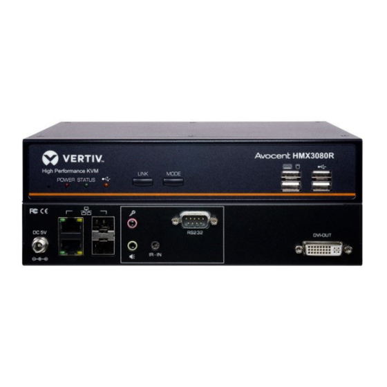
Vertiv™ HMX3080/HMX4080 series User Manual 6 Product Overview 6.1 HMX3080T/HMX3080R Figure 6.1 HMX3080T / HMX3080R Panels 6.2 HMX3080TP/HMX3080RP Figure 6.2 HMX3080TP / HMX3080RP Panels 6 Product Overview... - Page 20 Vertiv™ HMX3080/HMX4080 series User Manual Table 6.1 HMX3080 Description Item Description Reset Reset the unit. Power indicator Lights when power is on. Status indicator Lights when the connection between transmitter and receiver is active. LINK button Press to connect or disconnect between the transmitter and receiver.
-
Page 21: Hmx4080T/Hmx4080R
Vertiv™ HMX3080/HMX4080 series User Manual 6.3 HMX4080T/HMX4080R Figure 6.3 HMX4080T / HMX4080R Panels 6.4 HMX4080TP/HMX4080RP Figure 6.4 HMX4080TP / HMX4080RP Panels Table 6.2 HMX4080 Description Item Description Reset Reset the unit. Power indicator Lights when power is on. Status indicator Lights when the connection between transmitter and receiver is active. - Page 22 Vertiv™ HMX3080/HMX4080 series User Manual Table 6.2 HMX4080 Description (continued) Item Description Audio output jack Connect to a speaker. Power jack Connect to the power adapter. LAN port 1 Connect to the LAN port of TX, RX, or a Gigabit Ethernet Switch.
-
Page 23: Connection Diagram
Vertiv™ HMX3080/HMX4080 series User Manual 7 Connection Diagram The diagrams illustrated here are examples of Virtual Matrix KVM over IP, the actual applications may vary. All illustrated computers, accessories, and monitors are not included in the package, it is for reference only. -
Page 24: Before Connection
Vertiv™ HMX3080/HMX4080 series User Manual 7.1 Before Connection Before you install the Virtual Matrix KVM over IP, you should have these items on the checklist ready: Plan the layout path and deploy the UTP cable for extension. Plan the path through which the CAT5e/CAT6 UTP cable (or higher category network cable) will be deployed across the distance between the Transmitters and the Receivers. -
Page 25: Single Transmitter To Multiple Receivers
Vertiv™ HMX3080/HMX4080 series User Manual 7.2.2 Single Transmitter to Multiple Receivers The illustration shown here is using HMX3080 as an example and only highlighted the connection between the transmitter and receiver. To connect other peripherals, please refer to Figure 7.3 For the connection of HMX4080, you may take a reference of HMX3080. -
Page 26: Connection Via A Hub/Switch
Vertiv™ HMX3080/HMX4080 series User Manual 7.3 Connection via a Hub/Switch A Gigabit Ethernet Switch/Hub is necessary if the Network structure is forward to the matrix and expected more than 4 transmitters/receivers will be connected. Under a usage scenario like this, make sure the requirements listed in the chapter of Requirement of Gigabit Ethernet Switch below must be supported by the Hub/Switch. -
Page 27: Network Redundancy
Vertiv™ HMX3080/HMX4080 series User Manual 7.4 Network Redundancy HMX3080/HMX4080 Transmitter/Receiver Series supports Network Redundancy. Available configurations are shown below: 1. By connecting with two Gigabit Switches supporting STP (Spanning Tree Protocol) NOTE: (1) As TP model transmitters/RP model receivers are deployed in this application, please must connect the TX/RX units to their included power adaptors. - Page 28 Vertiv™ HMX3080/HMX4080 series User Manual Figure 7.8 Network Redundancy connection for HMX3080/HMX4080 Transmitter/Receiver Series 7 Connection Diagram...
-
Page 29: Operation
Vertiv™ HMX3080/HMX4080 series User Manual 8 Operation 1. Power on the transmitters, receivers ,and all the connected devices. 2. Long press (3s) the LINK button on the front panels of transmitters or receivers to make the connection. For more details, refer to the section description of . 8.1 1 Front panel buttons. -
Page 30: Led Indication
(USB) acquired the highest priority to be detected) 3. Ethernet Port LED Indications (HMX3080/HMX4080 Extender Series). As HMX3080T/HMX4080T and HMX3080R/HMX4080R are connected successfully via network connection, the Yellow LED is constantly ON and the Green LED is blinking. 8 Operation... -
Page 31: Keyboard Hotkeys
Vertiv™ HMX3080/HMX4080 series User Manual 8.1.3 Keyboard Hotkeys To select different PCs connected to transmitters from the receiver console, the keyboard hotkeys are provided. Each keyboard hotkey consists of at least three specific keystrokes. >> Hotkey sequence = < Scroll Lock, Scroll Lock, Command key(s) >... -
Page 32: Osd Menu
Vertiv™ HMX3080/HMX4080 series User Manual 8.2 OSD Menu Once you have completed the connection (refer to the chapter of connection diagram), press <Roll Lock, Scroll Lock, Space> hotkey to enter the OSD menu from the receiver console. Note: Double press left Ctrl key <Ctrl, Ctrl>... - Page 33 Vertiv™ HMX3080/HMX4080 series User Manual Figure 8.2 Proportional size 2. It shows the status of all users. The green user icon represents the user who is using the current receiver console. The grey user icons show other users connecting to those listed transmitters.
-
Page 34: Receiver Configuration
Vertiv™ HMX3080/HMX4080 series User Manual 8.3 Receiver Configuration Figure 8.3 Receiver The annotations in the Figure 8.3 above are as follows: 1. Device Name: User can change to a new receiver name for easy recognition. 2. Language: Drop down to select a preferred language. -
Page 35: Advanced Settings
Vertiv™ HMX3080/HMX4080 series User Manual 8. Factory default: Click to restore the receiver to the factory default settings, and then click OK to confirm. 9. Save: Click to save the settings once you have changed them. NOTE: (1) As you need to manually assign IP addresses for transmitter and receiver devices, please set up TX device before setting up RX device and make sure their IP addresses are in the same network segment. -
Page 36: Console Collaboration
Vertiv™ HMX3080/HMX4080 series User Manual 8.3.2 Console Collaboration HMX3080R(RP)/HMX4080R(RP) Receiver Unit Series supports the Console Collaboration function. With intuitive push/pull actions on the OSD, users can share a transmitter signal source that is being connected to a first receiver unit to a second receiver unit. Such that the second receiver unit can access the computer that is being connected to the transmitter unit, as the first receiver unit does. - Page 37 Vertiv™ HMX3080/HMX4080 series User Manual 8.4 Transmitter Configuration Figure 8.5 Transmitter 8 Operation...
- Page 38 Vertiv™ HMX3080/HMX4080 series User Manual The annotations in-Figure 8.5 on the previous page are as follows: 1. Double click on the monitor-icon of any desired transmitter to enter the setting page. 2. Device Name: User can change to a new transmitter name for easy recognition.
- Page 39 Vertiv™ HMX3080/HMX4080 series User Manual 8.5 Administrator’s OSD Menu Register devices under the HMXCC1 management interface: Go to Dashboard > Detected Devices to register one device. Select the device and click “+” symbol below to register it. Figure 8.6 Device Registration/ Device Language Once the HMX3080R/HMX4080R receivers have been registered, input the following administrator username and password to log in the receiver OSD menu.
- Page 40 Vertiv™ HMX3080/HMX4080 series User Manual Figure 8.7 Administrator’s OSD Login 8 Operation...
- Page 41 Vertiv™ HMX3080/HMX4080 series User Manual Figure 8.8 Administrator’s OSD Menu The receiver OSD menu of the administrator account as shown above will be described as follows: All the transmitters connected to the network will be displayed in this list. Administrator can search them page-by-page.
- Page 42 Vertiv™ HMX3080/HMX4080 series User Manual 6. Click to close the OSD menu. 7. Search all available transmitters page-by-page. 8 Operation...
- Page 43 Vertiv™ HMX3080/HMX4080 series User Manual 9 System Upgrade To update the system, a web user interface is provided. Users can easily access and configure what they need. Please follow the steps below for more operations. Contact with authorized service, local dealer or distributor for more support if you have trouble to update.
- Page 44 Vertiv™ HMX3080/HMX4080 series User Manual Figure 9.2 Firmware Update 1. Click Update Firmware to drop down more options. 2. Click Choose File to select the desired file, and then click Upload. 3. Please repeat the same upgrade procedure to other extender devices.
- Page 45 Vertiv™ HMX3080/HMX4080 series User Manual 10 Technical Support Please contact with your local distributor for more information or technical support. EN Version 1.0 Copyright © 2021 Vertiv, All Rights Reserved P/N: 30-191-HMX3080X-01-VTV-10 10 Technical Support...
- Page 46 Vertiv™ HMX3080/HMX4080 series User Manual This page intentionally left blank 10 Technical Support...
- Page 47 Vertiv™ HMX3080/HMX4080 series User Manual 11 FCC CE Statements FCC Statement: This equipment has been tested and found to comply with the regulations for a Class B digital device, pursuant to Part 15 of the FCC Rules. These limits are designed to provide reasonable protection against harmful interference when the equipment is operated in a commercial environment.
- Page 48 Vertiv™ HMX3080/HMX4080 series User Manual This page intentionally left blank 11 FCC CE Statements...
- Page 49 Vertiv™ HMX3080/HMX4080 series User Manual...
- Page 50 Vertiv.com | Vertiv Headquarters, 1050 Dearborn Drive, Columbus, OH, 43085, USA © 2022 Vertiv Group Corp. All rights reserved. Vertiv™ and the Vertiv logo are trademarks or registered trademarks of Vertiv Group Corp. All other names and logos referred to are trade names, trademarks or registered trademarks of their respective owners.
Need help?
Do you have a question about the HMX3080T and is the answer not in the manual?
Questions and answers