Table of Contents
Advertisement
Quick Links
102E-SM1110-00
SERVICE MANUAL
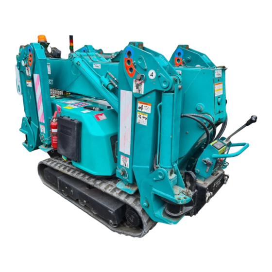
MINI-CRAWLER CRANE
Serial No. P00976 and up
The parts numbers and lists written in this service manual are the
references for the services such as disassembling and assembling.
Be sure to ALWAYS refer to the latest parts catalog (the latest
information) before ordering any part, since the parts and the model
numbers are subject to change during the endless improvements and
changes of our Machine.
Advertisement
Table of Contents
Troubleshooting

Related Manuals for Maeda MC285C-2


Summary of Contents for Maeda MC285C-2
- Page 1 102E-SM1110-00 SERVICE MANUAL MINI-CRAWLER CRANE Serial No. P00976 and up The parts numbers and lists written in this service manual are the references for the services such as disassembling and assembling. Be sure to ALWAYS refer to the latest parts catalog (the latest information) before ordering any part, since the parts and the model numbers are subject to change during the endless improvements and changes of our Machine.
- Page 3 SPECIFICATIONS System and Item MC285C-2 Machine weight 1960kg Overall length width 2750mm x 750mm x 1470mm height Weight and Distance between center dimensions 975mm idler and sprocket Track gauge 550mm Width of crawler 200mm Crane capacity 2.82t x 1.4m Performanc Maximum working radius 8.2m...
-
Page 4: Specification Dimensional Drawing
SPECIFICATION DIMENSIONAL DRAWING... -
Page 5: Dimensional Drawing Of Outrigger Width
DIMENSIONAL DRAWING OF OUTRIGGER WIDTH... -
Page 6: Rated Total Load Chart
RATED TOTAL LOAD CHART The Rated total load Chart is based on actual working radius with the bending of boom attributable to load reflected and is shown with the mass of hook block (30kg) included. RATED TOTAL LOAD CHART FOR 4 FALLS OUTRIGGER EXTENDED TO MAXIMUM 5.575m BOOM 7.075m BOOM... - Page 7 RATED TOTAL LOAD CHART FOR 2 FALLS OUTRIGGER EXTENDED TO MAXIMUM 2.535m/4.075m BOOM 5.575m BOOM 7.075m BOOM 8.575m BOOM Working Rated total Working Rated total Working Rated total Working Rated total radius (m) load (kg) radius (m) load (kg) radius (m) load (kg) radius (m) load (kg)
- Page 8 RATED TOTAL LOAD CHART FOR SINGLE FALL OUTRIGGER EXTENDED TO MAXIMUM 2.535m/4.075m BOOM 5.575m BOOM 7.075m BOOM 8.575m BOOM Working Rated total Working Rated total Working Rated total Working Rated total radius (m) load (kg) radius (m) load (kg) radius (m) load (kg) radius (m) load (kg)
-
Page 9: Working Radius And Lifting Height
WORKING RADIUS AND LIFTING HEIGHT... -
Page 10: Crane Operation
STANDARD PRESSURE AND OPERATING TIME CHART 1. OUTRIGGER (When Oil Temperature 45 – 55 °C) When Full Accelerating (2600min Operating Pressure (MPa) Operating time (sec) (At Travelling control valve) 18.6±1 25.4±2 Outrigger (1) 15.4±1 20.7±2 18.6±1 14.5±2 Outrigger (2) 15.4±1 20.0±2 18.6±1 13.5±2... - Page 12 B 1 2 # 0 4 A 1 2 B 1 0 B 1 1 A 1 1 A 1 0...
- Page 96 S O L 3 S O L 5 S O L 1 S O L 7 S O L 2 S O L 8 S O L 4 S O L 6 C N 1 C N 7 C N 1 C N 7 S O L 1 1 S O L 1 2...
-
Page 97: Moment Limiter
MOMENT LIMITER 1. MOMENT LIMITER RELATED 3- 2 2. OUTRIGGER SAFETY DEVICE 3-20 3. MOMENT LIMITER OVERVIEW AND FEATURES 3-27 4. EXTERNAL VIEW OF MOMENT LIMITER 3-28 5. BLOCK DIAGRAM 3-30 6. CONNECTOR DIAGRAM 3-31 7. CONNECTOR PIN ASSIGNMENT 3-32 8. -
Page 120: Angle Sensor
1.4.1 ANGLE SENSOR 3-10... -
Page 121: Specifications
Specifications 110°, min. Inclination Angle (98°, min. to plus range and 12°, min. to minus range, based on 0°of the chart above.) Total Accuracy ±1% under vibrating conditions (Including linearity and hysteresis). Approx. 1 second at Inclination angle 90° Response (Adequate under operation temperature conditions) Potentiometer (CP-2 or equivalent) Significant Electrical Angle... - Page 122 1.4.2 LENGTH SENSOR CODE REEL 3-12...
- Page 123 Description Q’ty Remarks Base Plate Case Drum Assembly Contact Cylinder Assembly Contact Assembly Potentiometer Case Packing O-ring Bracket Potentiometer NIPOSEAL, Seal Connector Gear Fasten Terminal (male) Sleeve Fasten Terminal (female) Sleeve Cable Guide Microphone Code Assembly Super lock Cable Stopper Caution Label 3-13...
-
Page 124: Pressure Sensors
1. 5.1 PRESSURE SENSORS Specifications/Capacity Working range 0 to 35 MPa Permissible pressure 52.5 MPa Power Supply Voltage 12V DC ±10% Power Form 1 to 5 DC 3 wires Load Resistance 10 K-ohm, min. ±0.1% F.S. Accuracy (Including linearity, hysteresis and repeatability at 23±2°C) Temperature ±0.1%F.S./ °C... - Page 125 MOMENT LIMITER OVERVIEW AND FEATURES Items MC-285C-US Type of Moment Limiter Automatic Cut Out Crane Rated Load 0 to 2.98 ton [Pressure Range: 0 to 20.6 MPa (0 to 210kg/cm Power Supply DC 12V (DC 10V – 15V) Display Panel 0.8 A (at DC 12V) Max.
-
Page 126: Display Unit
EXTERNAL VIEW OF MOMENT LIMITER DISPLAY UNIT... - Page 127 4.2 CONVERTER 3-29...
- Page 129 8. INPUT/OUTPUT 8.1 CONVERTER Direction Description Q’ty Specifications Pressure Sensor 1 Analog input [1 to 2.4V / 0 to 20.6 MPa (0 to 210kgf/cm )] Pressure Sensor 2 Analog input [1 to 2.4V / 0 to 20.6 MPa (0 to 210kgf/cm )] Length Sensor Analog input (0.72 to 3.07V / 0 to 4.5m) Angle Sensor...
-
Page 150: Error Messages
19. ERROR MESSAGES Any detectable errors cause “Rated Total Load Indicator” to display error codes. Criticality of errors shall be rated as A, B, C, D, or E, where A is most critical and gradually being reduced. Error Code Description Counter Measure Criticality Output to be “ON”... -
Page 151: Troubleshooting
20. TROUBLE SHOOTING In the event of malfunction, check each device in accordance with the Flow-Chart below: 3-72... - Page 152 3-73...
- Page 153 21. POINTS FOR INPUT VOLTAGE MEASUREMENT OF EACH SENSOR The drawing above is the motherboard for Converter. From top to bottom NF8: Angle Sensor NF9: Length Sensor NF7: Pressure Sensor 2 NF6: Pressure Sensor 1 Measure voltage between each of above points and GND. 3-74...
-
Page 154: Remote Control
REMOTE CONTROL 1. INITIAL MODE SETTING PROCEDURE 4- 2 2. RECEIVER 4-16 3. TROUBLESHOOTING 4-23... - Page 155 INITIAL MODE SETTING PROCEDURE 1.1 BUTTON ARRANGEMENT ON CONTROL PANEL *Alphabetical character on each button corresponds to the button name that appears in the following discussion.
- Page 156 1.2 ESTABLISHING INITIAL MODE: Example: Changing the setting of OFF timer from 5M to 10M. Retrieving the screen for initial mode 1. Use K and L buttons a few times so that cursor comes to the side of item you desire to set. 2.
- Page 157 F button until the screen of initial mode for user appears (For about 2 seconds). After “MAEDA RADIO REMOTE CONTROL” having appeared. Note: Be sure to turn OFF the main switch at receiver before starting to operate the initial mode.
- Page 158 2. Items for establishing the initial mode for user: (1) Contrast of LCD For adjusting the contrast of LCD. To make the contrast stronger: Press K button To make the contrast weaker: Press L button *At the time of factory shipment, the contrast is set to be optimum for in door use. (2) Voice Volume For adjusting the volume of voice message.
- Page 159 (7) Reset Micro Speed For resetting user’s Micro Speed rate to the initial value. N: Not reset setting value of the item to default. Y: Reset setting value of the item to default. (8) Version Version will be displayed.
- Page 160 N buttons pressed, continue to press F button until the screen of initial mode for user appears (For about 2 seconds). After “MAEDA RADIO REMOTE CONTROL” having showed up. ”B MODE” appears, before the prompt for password “PASS WORD 0000”...
- Page 161 2. Items for setting the initial mode for service: (1) Pattern Allow you to change the operating pattern. There are 3 patterns of STD, OPT or US patterns. At the time of factory shipment, this is set as US. STD pattern OPT pattern US pattern (2) Slew...
- Page 162 (4) Hook Stow For selection of availability of hook stowing function. Check the specifications of your crane. If it has the function, set is as ON. If not, set it as OFF. *At the time of factory shipment, this is set at ON. (5) Anti tow block device For selection of contacts A and B of anti two block device.
- Page 163 (10) Denomination Select to display unit on load display of transmitter. This is a selection of displaying “X1000lb” or not. “N” 1000lb is not displayed. “Y” 1000lb is displayed. * Pre-set from factory is “Y”.
- Page 164 F button until the screen of initial mode for maker appears (For about 2 seconds). After “MAEDA RADIO REMOTE CONTROL” having showed up. ”C MODE (Initial Mode for Maker)” appears, before the prompt for password “PASS WORD 0000” comes up.
- Page 165 2. Items for setting the initial mode for maker: (1) Model For selection of model. CAB: Track crane MIN 1: MC-104C, MC-235C, MC-285C MIN 1A: Not used. MIN 2: MC-305C, MC-305C-2, MC-405C MIN 2A: MC-583CF Not used. (2) Valve For selection of valve. There are 3 selections of “NSS50”, “SSC3A”...
- Page 166 (6) ID Code Not used. (7) Gain A setup of the revolution mentioned above, the gain value (Slew, Boom raising and lowering) “MID” and “LOW” can be performed. *Keep the value as “0” for reasons of the structure of the valve. (8) VR ON (Accelerator ON position) For setting of Accelerator ON position, in propotion to triggering ratio.
- Page 167 3. Adjustment of (8) VR ON and (9) FLOW ADJ Actuation range of the Accelerator may be changed, by adjusting (8) VR ON (Accelerator ON position) and (9) FLOW ADJ (Flow-control) as described above (1) Outline of VR ON (Accelerator ON position) Available range: 0 to 100 Value at the time of factory shipment: 40 Result...
- Page 168 (2) Outline of FLOW ADJ (Flow-control) The graph below shows the correlation with triggering ratio: Available range: 1 to 254 Value at the time of factory shipment: 120 Result When this value is increased, the timing of the flow rate (lever) to be maximum point shall become late, against triggering ratio Caution: Due to dispersion of each valve or power transformer, it may miss-function when the value is set to “0”.
- Page 169 (3) Adjustment of VR ON (Accelerator ON position) and FLOW ADJ (Flow-control) standard setting The graph below shows the correlation with triggering ratio: Comment: At first, when it is started triggered, only the flow rate (lever actuating ratio) increases. Just before the flow rate (lever actuating ratio) reaches its maximum point, the accelerator is started to be ON.
- Page 170 1.6 INITIAL MODE SETTING (For interactive remote controller) *High-light in “Selective Modes and Values” are the initial values. Selective Modes and Mode Setting Items Remarks Values LCD Contrast Optimum For indoors operation Voice Volume Accelerator 100% Bar chart indicator Light A MODE (For User) OFF Timer...
- Page 171 *High-light in “Selective Modes and Values” are the initial values. Selective Modes and Mode Setting Items Remarks Values MIN1 Model MIN2 MIN3 MIN4 NSS50 Micro Speed 1 0 This value is not effective. SSC3A VALVE Valve NACHI ERROR Error Indication, only COUNT Operation Time Number Indication, only...
- Page 175 LD25 LD24 LD21 LD23 LD13 LD12 LD14 LD16 LD19 LD20 LD22 LD11 LD15 LD17 LD18 CN12...
- Page 178 CN11 LD25 LD26 LD27 CN10 LD28 LD32 CN14 CN13 LD35 LD31 LD30 LD36 LD29 LD33 LD38 LD34...
-
Page 185: Electric Motor
ELECTRIC MOTOR 1. POWER UNIT 5- 2 2. INVERTER UNIT 5- 4 3. POWER SUPPLY BOX 5-18 4. ELECTRIC CIRCUIT DIAGRAM 5-20... -
Page 186: Principle Specification List
7. PRINCIPLE SPECIFICATION LIST System / Item MC285C-2E (Engine and Electric Motor Specifications) Machine weight 2120kg Overall length width 3320mm x 750mm x 1470mm height Weight and Distance between center 975mm dimensions idler and sprocket Track gauge 550mm Width of crawler 200mm Crane capacity 2.82t x 1.4m... -
Page 187: Specification Dimensinal Drawing
8. SPECIFICATION DIMENSINAL DRAWING 7-22... -
Page 188: Power Unit
3.2 POWER UNIT (1) Power unit cover (2) Electric motor (3) Coupling (4) Hydraulic pump 3.3 POWER SUPPLY BOX (1) Power supply box (2) Power supply box door (3) Door handle (4) Terminal block (5) Cable inserting hole... -
Page 189: Inverter Unit
3.4 INVERTER UNIT (1) Electric motor unit cover (5) AC circuit power switch (2) Protective cover (6) Power lamp (white) (3) Inverter unit (7) Trouble lamp (red) (4) DC12V power switch (8) Main breaker (with a leak detector) -
Page 190: Electric Motor Troubleshooting
6. ELECTRIC MOTOR TROUBLESHOOTING • Make sure that you contact us or our sales service agency for the actions indicated in the Actions fields. • Ask our sales service agency for repair if you suspect any other abnormalities or causes than those given below. -
Page 195: Name And Function
2.2 NAME AND FUNCTION Run lamp STOP key PRG lamp Built-in potentiometer MON lamp Enter key Percent (%) lamp MODE key Hertz (Hz) lamp Built-in potentiometer lamp Up key Charge lamp Up/Down key lamp Front panel Down key Unlock position mark RUN key lamp Panel locking screw RUN key... - Page 196 Run lamp Lights when an ON command is issued but no frequency signal is sent out it blinks when operation is started. PRG lamp Lights when the inverter is in parameter setting mode. Blinks when the inverter is placed in AUH Gr. U mode. MON lamp Lights when the inverter is in monitor mode.
-
Page 197: Trip Causes/Warnings And Remedies
2.3 TRIP INFORMATION AND REMEDIES 2.3.1 TRIP CAUSES/WARNINGS AND REMEDIES When a problem arises, diagnose it in accordance with the following table. If it is found that replacement of parts is required or the problem cannot be solved by any remedy described in the table, contact your Toshiba dealer. - Page 198 (Continued) Failure Error code Problem Possible cause Remedies code ・The input voltage fluctuates abnormally. ・Insert a suitable input reactor. 000A Over-voltage during acceleration (1) The power supply has a capacity of 200kVA or more. (2) A power factor improvement capacitor is opened or dosed.
- Page 199 (Continued) Failure Error code Problem Possible cause Remedies code ・An external thermal trip is input. ・Check the external thermal input. 002E External thermal trip ・ During automatic operation or remote ・Reset the inverter. 0011 Emergency stop operation, a stop command is entered from the operation panel or a remote input device.
- Page 200 [ALARM INFORMATION] Each message in the table is displayed to give warning but does not cause the inverter to trip. Error code Problem Possible cause Remedies ・ The ST-CC circuit is opened. ・Close the ST-CC circuit. ST terminal OFF ・The supply voltage between R, S and T is ・Measure the main circuit supply voltage.
- Page 201 2.3.2 RESTORING THE INVERTER FROM A TRIP Do not reset the inverter when tripped because of a failure or error before eliminating the cause. Resetting the tripped inverter before eliminating the problem causes it to trip again. The inverter can be restored from a trip by any of the following operations: (1) By turning off the power (Keep the inverter off until the LED turns off.) (2) By means of an external signal (Short circuit between RES and CC on terminal board →...
- Page 202 2.3.3 IF THE MOTOR DOES NOT RUN WHILE NO TRIP MESSAGE IS DISPLAYED… If the motor does not run while no trip is displayed, follow these steps to track down the cause. The motor does not run. YES: NO : Is the 7-segment LED extinguished? Supply the power normally.
- Page 203 2.3.4 HOW TO DETERMINE THE CAUSES OF OTHER PROBLEMS The following table provides a listing of other problems, their possible causes and remedies. Problems Causes and remedies ・Inverter the phases of the output terminals U, V and W. The motor runs in the wrong direction.
-
Page 204: Inspection And Maintenance
2.4 INSPECTION AND MAINTENANCE DANGER • The equipment must be inspected every day. If the equipment is not inspected and maintained, error and malfunctions may not be discovered which could lead to accidents. •Before inspection, perform the following steps. (1) Shut off all input power to the inverter. -
Page 205: Periodical Inspection
2.4.2 PERIODICAL INSPECTION Make a periodical inspection at intervals 3 or 6 months depending on the operating conditions. DANGER •Before inspection, perform the following steps. (1) Shut off all input power to the inverter. (2) Wait at least ten minutes and check to make sure that the change lamp is no longer lit. (3) Use a tester that can measure DC voltages (800V DC or more), and check that the voltage to the DC Mandatory main circuits (across PA-PC) does not exceed 45V. -
Page 206: Disposal Of The Inverter
Note: The operation time is helpful for roughly determining the time of replacement. For the replacement of parts, contact your nearest Maeda distributor. For safety’s sake, never replace any part on your own. (Parts replacement alarms can be known by monitor and alarm output, if it is set.) ■... - Page 207 MAEDA MINI-CRAWLER CRANE MC285C-2 SERVICE MANUAL Document No: 102E-SM1110-00 First edition: October 26, 2011 Issued by Maeda Seisakusyo Co., Ltd. 1095 Onbegawa, Shinonoi Nagano, Nagano 388-8522, Japan No part of this manual can be reproduced in any from without permission...
Need help?
Do you have a question about the MC285C-2 and is the answer not in the manual?
Questions and answers