Table of Contents
Advertisement
Quick Links
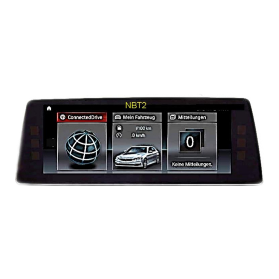
with NBT2 and 6.5, 7, 8.8 and 10.25inch monitor and HSD+2 plug
with NBT2 8.8inch monitor and HSD+2 plug
Video-inserter for one rear-view camera
Product features
Video-inserter for factory-infotainment systems
CVBS Input for one rear-view camera
2 CVBS Video-inputs for after-market Video sources (e.g. DVD-Player, DVB-T Tuner)
Automatic switching to rear-view camera input on engagement of the reverse gear
Activatable parking guide lines for rear-view camera (not available for all vehicles)
Video-in-motion (ONLY for connected video-sources)
Video-inputs NTSC and PAL compatible
Version 07.11.2018
r.LiNK Video inserter
CI-RL3-NBT2
CI-RL3-NBT2-10
Compatible with
BMW
vehicles F-and G-series
Mini
vehicles
and two additional video inputs
HW: CAM(V97)/(V14)
CI-RL3-NBT2 /CI- Rl3-NBT2-10
Advertisement
Table of Contents

Related Manuals for Car-Interface.com CI-RL3-NBT2


Summary of Contents for Car-Interface.com CI-RL3-NBT2
- Page 1 Automatic switching to rear-view camera input on engagement of the reverse gear Activatable parking guide lines for rear-view camera (not available for all vehicles) Video-in-motion (ONLY for connected video-sources) Video-inputs NTSC and PAL compatible Version 07.11.2018 HW: CAM(V97)/(V14) CI-RL3-NBT2 /CI- Rl3-NBT2-10...
-
Page 2: Table Of Contents
Case 2: Interface does not receive the reverse gear signal 2.6. Connection - video-interface and external keypad 2.7. Picture settings and guide lines 3. Interface operation 3.1. By factory infotainment button 3.2. By keypad 4. Specifications 5. FAQ – Trouble Shooting-Interface functions Version 07.11.2018 HW: CAM(V97)/(V14) CI-RL3-NBT2 /CI- Rl3-NBT2-10... -
Page 3: Prior To Installation
Due to changes in the production of the vehicle manufacturer there’s always a possibility of incompatibility. 1.1. Delivery contents 'ahmad@fosp.cn' Take down the serial number of the interface and store this manual for support purposes: ____________________ Version 07.11.2018 HW: CAM(V97)/(V14) CI-RL3-NBT2 /CI- Rl3-NBT2-10... -
Page 4: Checking The Compatibility Of Vehicle And Accessories
To delay the switch-back an additional electronic part is required. PDC and guidelines If the video interface does not receive the required information from the vehicle CAN-bus, neither guide-lines nor optical PDC display will be supported. Version 07.11.2018 HW: CAM(V97)/(V14) CI-RL3-NBT2 /CI- Rl3-NBT2-10... -
Page 5: Boxes And Connectors - Video Interface
Try all possible combinations of Dips 7 and 8 to receive Monitor the best picture (quality and size) or adjustments see chapter “Monitor selection (dip 7 and 8)” See the following chapters for detailed information. Version 07.11.2018 HW: CAM(V97)/(V14) CI-RL3-NBT2 /CI- Rl3-NBT2-10... -
Page 6: Activating The Pdc Function (Dip 1)
7inch monitor dip 7+8 to find the best picture (in quality and size) 8,8inch monitor 10.25inch monitor Note: For 10.25 inch monitor, the picture signal cable CAB-HSD2-DF100 has to be used. Version 07.11.2018 HW: CAM(V97)/(V14) CI-RL3-NBT2 /CI- Rl3-NBT2-10... -
Page 7: Installation
Due to changes in the production of the vehicle manufacturer there’s always a possibility of incompatibility. 2.1. Place of installation The interface is supposed to be installed at a suitable location behind the vehicle`s head- unit. Version 07.11.2018 HW: CAM(V97)/(V14) CI-RL3-NBT2 /CI- Rl3-NBT2-10... -
Page 8: Connection Schema
2.2. Connection schema Version 07.11.2018 HW: CAM(V97)/(V14) CI-RL3-NBT2 /CI- Rl3-NBT2-10... -
Page 9: Connection To Factory Head Unit And Monitor
However, mixing up/interchanging the connections of „HU IN“ and „TO LCD“ will cause dysfunktion or even damage to the system! Note: The colours of the HSD+2 connectors at monitor and head unit may vary. Version 07.11.2018 HW: CAM(V97)/(V14) CI-RL3-NBT2 /CI- Rl3-NBT2-10... -
Page 10: Rl3-Nbt2-10
However, mixing up/interchanging the connections of „HU IN“ and „TO LCD“ will cause dysfunktion or even damage to the system! Note: The colours of the HSD+2 connectors at monitor and head unit may vary. Version 07.11.2018 HW: CAM(V97)/(V14) CI-RL3-NBT2 /CI- Rl3-NBT2-10... -
Page 11: Connection - Quadlock/Can
Power / CAN cable. Connect the opposite female Quadlock connector of the 10pin PNP Power / CAN cable to the previously become free male Quadlock connector at the rear-side of the head unit. Version 07.11.2018 HW: CAM(V97)/(V14) CI-RL3-NBT2 /CI- Rl3-NBT2-10... -
Page 12: Analog Power Supply For The Video Interface
Connect the red coloured wire ACC-out (max 3A) and the purple coloured wire Manual ACC of the 12pin interface cable both to S-contact terminal 86s +12V (e.g. glove compartment illumination). Version 07.11.2018 HW: CAM(V97)/(V14) CI-RL3-NBT2 /CI- Rl3-NBT2-10... -
Page 13: Connection - Video-Sources
Connect the video RCA of the video source 1 and 2 to the female RCA connector “Video IN1” ”Video IN 2” of the 12pin interface cable. Connect the video RCA of the rear-view camera to the 12pin interface cable’s female RCA connector “Camera IN”. Version 07.11.2018 HW: CAM(V97)/(V14) CI-RL3-NBT2 /CI- Rl3-NBT2-10... -
Page 14: Audio Insertion
“Camera IN” while the reverse gear is engaged. Additionally, the +12V (max. 3A) power supply for the rear-view camera can be taken from the green wire of the 12pin interface cable. Version 07.11.2018 HW: CAM(V97)/(V14) CI-RL3-NBT2 /CI- Rl3-NBT2-10... -
Page 15: Case 2: Interface Does Not Receive The Reverse Gear Signal
Connect the output connector (87) of the relay to the rear-view camera’s power- cable, like you did it to the green “Reverse-IN” cable before. Connect stabile and permanent +12V to the relay’s input connector (30). Version 07.11.2018 HW: CAM(V97)/(V14) CI-RL3-NBT2 /CI- Rl3-NBT2-10... -
Page 16: Connection - Video-Interface And External Keypad
Connect the female 4pin connector of the keypad to the male 4pin connector of the 12pin interface cable. Note: Even if switching through several video sources by the keypad mightn’t be required, the invisible connection and availability is strongly recommended. Version 07.11.2018 HW: CAM(V97)/(V14) CI-RL3-NBT2 /CI- Rl3-NBT2-10... -
Page 17: Picture Settings And Guide Lines
If there is no communication between interface and the vehicle`s CAN-bus (several vehicles aren’t compatible), the reverse gear guide-lines can`t be shown during the vehicle’s operation, even if they once appear after having switched the system to powerless! Version 07.11.2018 HW: CAM(V97)/(V14) CI-RL3-NBT2 /CI- Rl3-NBT2-10... -
Page 18: Interface Operation
Alternatively or additionally to the factory infotainment buttons, the interface’s external keypad can be used to switch the enabled inputs. Even if not needed, the keypad should always remain connected to the video interface for support purposes. Version 07.11.2018 HW: CAM(V97)/(V14) CI-RL3-NBT2 /CI- Rl3-NBT2-10... -
Page 19: Specifications
10mA Power 320mA @12V Video input 0.7V - 1V Video input formats NTSC and PAL Temperature range -40°C to +85°C Dimensions video-box 112 x 22 x 115 mm (W x H x D) Version 07.11.2018 HW: CAM(V97)/(V14) CI-RL3-NBT2 /CI- Rl3-NBT2-10... -
Page 20: Faq - Trouble Shooting-Interface Functions
Test camera under natural light outside the garage. flickers. directly into the camera. Camera input picture is Protection sticker not Remove protection sticker from lens. bluish. removed from camera lens. Version 07.11.2018 HW: CAM(V97)/(V14) CI-RL3-NBT2 /CI- Rl3-NBT2-10... - Page 21 Interface switches compatibility to vehicle is ends. If problem still occurs, additionally cut the white video-sources by itself. limited. wire of 6pin to 8pin cable and isolate both ends. 10R-03 5384 Made in China Version 07.11.2018 HW: CAM(V97)/(V14) CI-RL3-NBT2 /CI- Rl3-NBT2-10...
Need help?
Do you have a question about the CI-RL3-NBT2 and is the answer not in the manual?
Questions and answers