Table of Contents
Advertisement
Quick Links
r.LiNK Video inserter
CI-RL4-MBN55
Compatible with Mercedes Benz vehicles with
Comand Online NTG5.5 with 10.25inch or 12inch monitor
and Audio 20 NTG5.5 with 7inch or 8.4inch monitor
with double Fakra connector at the head unit
Video-inserter for front- and rear-view camera
and two additional video inputs
Product features
Video-inserter for factory-infotainment systems
1 CVBS Input for rear-view camera
1 CVBS Input for front camera
2 CVBS Video-inputs for after-market Video sources (e.g. USB-Player, DVB-T Tuner)
Automatic switching to rear-view camera input on engagement of the reverse gear
Automatic front camera switching after reverse gear for 10 seconds
Activatable parking guide lines for rear-view camera (not available for all vehicles)
Video-in-motion (ONLY for connected video-sources)
Video-inputs NTSC and PAL compatible
Version 19.03.2020
HW: GD(V100)/(V46)
CI-RL4-MBN55
Advertisement
Table of Contents

Subscribe to Our Youtube Channel
Related Manuals for Car-Interface.com r.LiNK


Summary of Contents for Car-Interface.com r.LiNK
- Page 1 Video inserter CI-RL4-MBN55 Compatible with Mercedes Benz vehicles with Comand Online NTG5.5 with 10.25inch or 12inch monitor and Audio 20 NTG5.5 with 7inch or 8.4inch monitor with double Fakra connector at the head unit Video-inserter for front- and rear-view camera...
-
Page 2: Table Of Contents
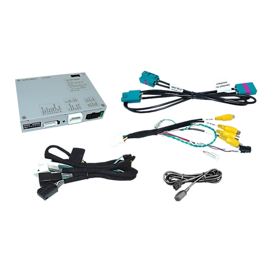
Contents 1. Prior to installation 1.1. Delivery contents 1.2. Checking the compatibility of vehicle and accessories 1.3. Boxes and connectors – video interface 1.4. Settings of the 8 dip switches (black) 1.4.1. Activating the front camera (dip 1) 1.4.2. Enabling the interface’s video inputs (dip 2-3) 1.4.3. -
Page 3: Prior To Installation
Legal Information By law, watching moving pictures while driving is prohibited, the driver must not be distracted. We do not accept any liability for material damage or personal injury resulting, directly or indirectly, from installation or operation of this product. Apart from using this product in an unmoved vehicle, it should only be used to display fixed menus or rear-view- camera video when the vehicle is moving (for example the MP3 menu for DVD upgrades). -
Page 4: Checking The Compatibility Of Vehicle And Accessories
1.2. Checking the compatibility of vehicle and accessories Requirements Brand Compatible vehicles Compatible systems C-class (W205) since about 07/2018 CLS-Coupé (C257) since 02/2018 E-class (W213) since 06/2016 Comand Online NTG 5.5 with E-class Coupé (A/C238) since 09/2017 10.25inch or 12inch monitor Mercedes Benz G-model (G463) since 05/2018 Audio 20 NTG 5.5 with... -
Page 5: Boxes And Connectors - Video Interface
1.3. Boxes and connectors – video interface The video-interface converts the video signals of connected after-market sources in a factory monitor compatible picture signal which is inserted in the factory monitor, by using separate trigger options. Further it reads the vehicle’s digital signals out of the vehicle’s CAN-bus and converts them for the video interface. -
Page 6: Settings Of The 8 Dip Switches (Black)
1.4. Settings of the 8 Dip switches (black) Some settings have to be selected by the dip-switches on the video interface. Dip position UP = OFF DOWN = Function ON (down) OFF (up) Front camera enabled* disabled Power supply +12V (max. 3A) when reverse output gear is engaged incl. -
Page 7: Activating The Front Camera (Dip 1)
1.4.1. Activating the front camera (dip 1) If set to ON, the interface switches for 10 seconds from the rear-view camera to the front camera input after having disengaged the reverse gear. In addition, a manual switch-over to the front camera input is possible via keypad (short press) from any image mode. Description of the power supply output: see chapter “Power supply output”. -
Page 8: Settings - 6 Dip Switches (Top Of Box-Black)
1.5. Settings - 6 Dip switches (Top of box–black) The 6 dip switches at the top of the video interface are responsible for the according monitor assignment. Attention: In contrast to both other dip benches (8dip and 4dip), the 6dip position UP = ON DOWN = OFF! -
Page 9: Installation
2. Installation To install the interface, first switch off the ignition and disconnect the vehicle’s battery. Please read the owner`s manual of the car, regarding the battery`s disconnection! If required, enable the car`s Sleep-mode (hibernation mode) In case the sleep-mode does not succeed, the disconnection of the battery can be done with a resistor lead. -
Page 10: Connection Schema
2.2. Connection schema Version 19.03.2020 HW: GD(V100)/(V46) CI-RL4-MBN55... -
Page 11: Connection - Factory Head Unit
2.3. Connection - factory head-unit Remove the head unit 2.3.1. Connection - factory head-unit 2.3.1.1. Standard connection - picture signal cable (ocher coloured double Fakra) Connect the picture signal cable’s green female double Fakra connector to the male double Fakra connector of the video interface. Disconnect the ocher-coloured female double Fakra connector from the rear-side of the... -
Page 12: Special Case: Connection - Picture Signal Cable
2.3.1.2. Special case: Connection - picture signal cable (blue coloured double Fakra As there are several Audio 20 NTG 5.5 head units without that ocher-coloured double Fakra connector, this connection has to be done at the blue coloured double Fakra connector. Connect the picture signal cable’s female green coloured double Fakra connector to the... -
Page 13: Connection - Quadlock - Can
2.3.2. Connection - Quadlock - CAN Connect the female 10pin connector of the 10pin Power / CAN cable to the 10pin connector of the video interface. Remove the female Quadlock connector of the vehicle harness from the rear-side of the head-unit and connect the previously clipped out white and black female 12pin connectors to the white and black male 12pin connector of the PNP harness (see graphic). -
Page 14: Power/Can Connection For The Video Interface
2.4. Power/CAN connection for the video interface Connect the single yellow wire of the 10pin power/CAN cable to +12V permanent and stabile power supply. Connect the single black wire of the 10pin power/CAN cable to the vehicle’s negative ground. Version 19.03.2020 HW: GD(V100)/(V46) CI-RL4-MBN55... -
Page 15: Analog Power Supply For The Video Interface
2.5. Analog power supply for the video interface If, after connecting the PNP harness, no interface LED lightens up while the ignition is turned on, the purple coloured wire Manual ACC of the 12pin interface cable has to be connected additionately to S-contact terminal 86s +12V (e.g. -
Page 16: Power Supply Output
2.6. Power supply output The red power supply output ACC/front cam out 12V (max 3A) can be used to power an external source and has a different assignment depending on the position of dip switch 1 (of the black 8 dips): Function Dip 1 ON +12V (max. -
Page 17: Connection - Video-Sources
2.7. Connection - video sources It is possible to connect an after-market rear-view camera, an after-market front camera and two more video sources to the video-interface. Before a final installation of the video sources, we recommend a test-run to ensure the compatibility of vehicle and interface. -
Page 18: Audio Insertion
2.7.1. Audio-insertion This interface is only able to insert video signals into the factory infotainment. If an AV- source is connected, the audio insertion has to be done by the factory audio AUX input or an FM-modulator. The inserted video-signal can be activated simultaneously to each audio- mode of the factory infotainment. -
Page 19: After-Market Rear-View Camera
2.7.3. After-market rear-view camera Some vehicles have a different reverse gear code on the CAN-bus which the video-interface is not compatible with. Therefore, there are two different ways of installation. If the video interface receives a signal of the reverse gear, the green wire “Reverse-OUT”... -
Page 20: Case 2Interface Does Not Receive The Reverse Gear Signal
2.7.3.2. Case 2: Interface does not receive the reverse gear signal If the video interface does not deliver +12V on the green wire of the 12pin cable when reverse gear is engaged (not all vehicles are compatible), an external switching signal from the reverse gear light is required. -
Page 21: Connection - Video-Interface And External Keypad
2.8. Connection - video-interface and keypad Connect the female 4pin connector of the keypad to the male 4pin connector of the 12pin interface cable. Note: Even if switching through several video sources by the keypad mightn’t be required, the invisible connection and availability is strongly recommended. Version 19.03.2020 HW: GD(V100)/(V46) CI-RL4-MBN55... -
Page 22: Picture Settings And Guide Lines
2.9. Picture settings and guide lines The picture settings are adjustable by the 3 push-buttons at the rear-side of the video- interface. Press the MENU button to open the OSD settings menu or to switch to the next menu item. Press UP and DOWN to change the selected value. The buttons are placed inside in the housing to avoid accidental changes during or after the installation. -
Page 23: Interface Operation
3. Interface operation 3.1. By factory infotainment button To switch the interface’s activated video sources, the factory infotainment’s menu or Navi buttons can be used. To change the CLS 2018 video sources, the center console’s “BACK” button can be used. Pressing the according infotainment button switches the input from the factory video to the inserted video sources. -
Page 24: By Keypad
3.2. By keypad Alternatively or additionally to the factory infotainment buttons, the interface’s external keypad can be used to switch the enabled inputs. Even if not needed, the keypad should always remain connected to the video interface for support purposes. ... -
Page 25: Faq - Trouble Shooting-Interface Functions
FAQ – Trouble shooting Interface functions For any troubles which may occur, check the following table for a solution before requesting support from your vendor. Symptom Reason Possible solution Not all connectors have been reconnected to factory head- Connect missing connectors. unit or monitor after installation. - Page 26 Symptom Reason Possible solution Camera input picture Use relay or electronics to "clean" reverse gear lamp black. Camera power taken directly power. Alternatively, if CAN-bus box is compatible Camera input picture from reverse gear lamp. with the vehicle, camera power can be taken from green wire of 6pin to 8pin cable.
Need help?
Do you have a question about the r.LiNK and is the answer not in the manual?
Questions and answers