Advertisement
USER Manual
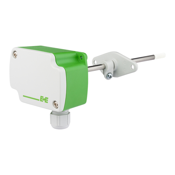
EE150 - Humidity and Temperature Sensor for HVAC applications
Find this document and further product information on our website at www.epluse.com/ee150.
SCOPE OF SUPPLY
•
EE150 sensor, type number according to order (for ordering guide see data sheet at www.epluse.com/ee150)
•
Cable gland M16 x 1.5
•
Mounting flange, PC, Ø 6.0mm (with Type T2)
•
Test report according to DIN EN 10204-2.2
CAUTION
•
For accurate measurement it is essential that the temperature of the probe and mainly of the sensing head is same as the
temperature of the air to measure.
•
Avoid mounting the EE150 sensor in a way which creates temperature gradients along the probe. If possible, EE150 shall be
installed with the entire probe inside the duct. For installation with mounting flange, in case of different temperature inside and
outside the duct, the probe part outside the duct shall be thermally isolated.
•
The device and mainly the sensing head shall not be exposed to extreme mechanical stress.
•
Do not attempt to remove the filer cap, which is fixed. Avoid touching the sensing head at all times.
•
The stainless steel probe is ESD sensitive and shall be handled as such. Do not connect it to the ground potential.
CONNECTION DIAGRAM
EE150-M1A3xx
Setup And Adjustment interface (with EE-PCA)
EE150-M1A6xx
setup and adjustment interface (with EE-PCA)
DIMENSIONS / MOUNTING
Values in mm (inch)
Duct mount
drilled hole for
mounting: ø>9
(class III)
(class III)
ø 4
ø 5
Wall mount
CABLE GLAND M16x1.5
80.8
(3.18)
39.5
(1.56)
63
(2.48)
M12x1.5
M16x1.5
Advertisement
Table of Contents

Related Manuals for E+E Elektronik EE150


Summary of Contents for E+E Elektronik EE150
- Page 1 • Avoid mounting the EE150 sensor in a way which creates temperature gradients along the probe. If possible, EE150 shall be installed with the entire probe inside the duct. For installation with mounting flange, in case of different temperature inside and outside the duct, the probe part outside the duct shall be thermally isolated.
- Page 2 1) USA & Canada class 2 supply required, max. supply voltage 30 V DC. SETUP AND ADJUSTMENT The EE150 is ready to use and does not require any configuration by the user. The factory setup of EE150 corresponds to the type num- ber ordered. For ordering guide please see data sheet at www.epluse.com/ee150.
Need help?
Do you have a question about the EE150 and is the answer not in the manual?
Questions and answers